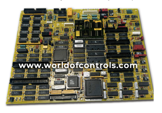
World Of Controls understands the criticality of your requirement and works towards reducing the lead time as much as possible.
DS200TCCAG1BAA - TC2000 Common Analog I/O Board is available in stock which ships the same day.
DS200TCCAG1BAA - TC2000 Common Analog I/O Board comes in UNUSED as well as REBUILT condition.
To avail our best deals for DS200TCCAG1BAA - TC2000 Common Analog I/O Board, contact us and we will get back to you within 24 hours.
SPECIFICATIONS:
Part Number: DS200TCCAG1BAA
Manufacturer: General Electric
Series: Mark V
Product Type: TC2000 Common Analog I/O Board
Mounting Location: R5 Core
Communication Connector: 3PL
Input Signal Types: 4�20 mA
Output Signal Type: 4�20 mA
Output Connectors: JAA
Repair: 3-7 days
Weight: 0.45 kg
Dimension: 28 cm x 18 cm
Availability: In Stock
Country of Origin: United States
FUNCTIONAL DESCRIPTION:
DS200TCCAG1BAA is a TC2000 Common Analog I/O Board manufactured and designed by General Electric as part of the Mark V Series used in GE Speedtronic Gas Turbine Control Systems. The Common Analog I/O Board (TCCA), located in the
TCCA CONFIGURATION:
Hardware: The TCCA board has three hardware jumpers ñ J1, JP2, and JP3. J1 is used to enable/disable the serial RS232 port. JP2 disables the oscillator for card test. JP3 is used for factory testing.
Software: I/O configuration constants for the thermocouples, RTDs, mA inputs and outputs, and the shaft voltage and current settings are entered in the I/O Configuration Editor located on the HMI as described below.
TCCA 4 - 20 mA INPUT CIRCUIT:
The TCCA board provides the circuitry for the 4ñ20 mA input signals. The signals are read from the CTBA terminal board via the JBB connector. The transducer current is dropped across a burden resistor, and the voltage drop is read by the TCCA board and written to the I/O Engine via the 3PL connector.
TCCA 4 - 20 mA INPUT CIRCUIT:
The TCCA board provides the circuitry for driving 4ñ20 mA outputs to the CTBA terminal board via the JAA connector. These signals are typically used to drive remote instrumentation for monitoring.
TCCA TRD CIRCUIT:
The circuitry that supplies excitation to the RTDs from the TBCA terminal board is located on the TCCA board. A steady current is sent through the RTD, and when the temperature changes, the resistance changes, causing the voltage on the RTD to change. The TCCA board measures, scales, and conditions the voltage signal. The RTD signals are read from the TBCA terminal board by the TCCA board over the JCC and JDD connectors. The TCCA board sends the signals to the I/O Engine via the 3PL connector. The type of RTD is selected using I/O configuration constants.
TCCA THERMOCOUPLE CIRCUIT:
The TBQA terminal board reads the thermocouple inputs. The cold junction circuitry on the TBQA terminal board provides the cold junction signals. The TCCA board uses these values to calculate the cold junction compensation. The TCCA board uses the thermocouple input and compensation value to calculate the actual temperature read by the thermocouple. The I/O Engine reads the value via the 3PL connector. Thermocouple types and curves are selected using I/O configuration constants.
TCCA SHAFT MONITORING:
The monitoring for the turbine shaft voltage and current is provided by the TCCA board. These signals are read from the CTBA terminal board via the JBB connector. The signals are written to the I/O Engine via the 3PL connector.
WOC has the largest OEM Replacement Parts for Speedtronic Gas Turbine Control Systems stock. We can also repair your faulty boards and supply unused and rebuilt boards backed up with a warranty. Our team of experts is available around the clock to support your OEM needs. Our team of experts at WOC is happy to assist you with any of your automation requirements. For pricing and availability on parts and repairs, kindly contact our team by phone or email.
How does the TCCA board manage signal conditioning from multiple terminal boards within the
The TCCA board collects analog signals from the CTBA, TBQA, and TBCA terminal boards. It then conditions these signals—whether they’re current loops, RTDs, or thermocouples—and standardizes them for communication with the I/O Engine through the 3PL connector.
What role does the 3PL connector play in system communication for the TCCA board?
The 3PL connector acts as the primary data bridge, transmitting all conditioned analog inputs from the TCCA board to the I/O Engine, enabling real-time monitoring and control.
Why is jumper JP2 important during board testing procedures?
JP2 disables the onboard oscillator, making it a key hardware setting when conducting specific card-level diagnostic or factory tests.
How does the TCCA board differentiate and handle various RTD types during operation?
The RTD type is selected via I/O configuration constants. The board uses fixed excitation current and measures voltage changes due to resistance variations, scaling the values accordingly.