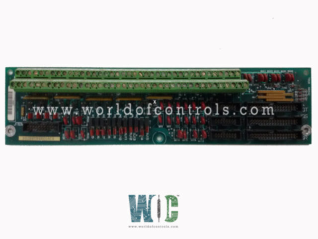
SPECIFICATIONS
Part No.: DS200TBQBG1ABB
Manufacturer: General Electric
Country of Manufacture: United States of America (USA)
Product Type: Input Termination Module
Availability: In Stock
Series: Mark V
Functional Description
DS200TBQBG1ABB is an input termination module developed by GE. It is a part of the Mark V control system. The Input Termination Module plays a role in handling specific input signals within the R2 and R3 cores. The input termination module located in both the R2 and R3 cores is instrumental in managing and processing voltage, vibration, and pulse rate input signals. Its connections to TCQA and TCQC boards enable seamless data transmission and integration within the cores, contributing to enhanced operational efficiency and effective condition monitoring of the systems.
Features
- The terminal board is situated in location seven of both the R2 and R3 cores.
- R2 Core: In the R2 core, the TBQB terminal board is connected to the TCQA and TCQC boards located in the R1 core. This connection facilitates the transmission of input signals between the R2 and R1 cores, ensuring seamless integration of data.
- R3 Core: Similarly, in the R3 core, the TBQB terminal board is connected to the TCQA and TCQC boards within the same R3 core. This setup allows for efficient handling and processing of input signals directly within the R3 core environment.
Handled Input Signals
The terminal board is primarily responsible for managing the following types of input signals:
- Voltage Inputs: Signals related to voltage measurements, which are crucial for monitoring electrical parameters within the system.
- Vibration Inputs: Signals indicating vibration levels, often used for condition monitoring of machinery and equipment.
- Pulse Rate Inputs: Signals that measure the frequency or rate of pulses, which can indicate operational cycles or events.
Signal Processing and Integration
- The terminal board serves as a central hub where these input signals are landed and processed. By connecting to TCQA and TCQC boards in their respective cores, the board ensures that voltage, vibration, and pulse rate inputs are efficiently transmitted and integrated into the broader system architecture. This integration supports real-time monitoring, analysis, and control of critical parameters essential for operational performance and maintenance planning.
Hardware Configuration
- In system hardware configuration, several jumpers, specifically BJ1 through BJ15, play crucial roles in tailoring input signals for diverse applications. These jumpers are designed to manage and adapt analog inputs, particularly focusing on pressure transducer #1 and general analog signal handling.
- BJ1 through BJ4 are employed in older applications to fan out the input signal from pressure transducer #1. This setup allows the signal to be distributed across multiple points within the system, enabling comprehensive monitoring and analysis where signal replication is necessary for redundancy or extensive data collection.
- Complementing BJ1 through BJ4, BJ5 through BJ7 are utilized to modify the pressure transducer #1 input signal from a voltage-based to a current-based format. By installing a burden resistor, these jumpers convert the signal to milliamps (mA), enhancing compatibility with systems that require current-driven inputs for precise measurement and control.
- For broader system flexibility, BJ8 through BJ15 provide configuration options for analog inputs, allowing them to be set either for current (mA) or voltage signals. This versatility ensures that the system can adapt to various sensor types and operational requirements without the need for extensive hardware modifications, thus optimizing integration and performance across different applications.
- These hardware configurations are integral to optimizing system functionality and performance in industrial environments, where accurate and adaptable signal processing is essential for monitoring critical parameters and ensuring operational efficiency and safety.
The WOC team is always available to help you with your Mark V requirements. For more information, please contact WOC.
Frequently Asked Questions
What is DS200TBQBG1ABB?
It is an input termination module developed by GE under the Mark V series.
How do BJ5 through BJ7 modify the pressure transducer 1 input signal?
BJ5 through BJ7 install a burden resistor to the pressure transducer 1 input signal, converting it from a voltage signal to a current signal measured in milliamps (mA). This conversion is beneficial for applications requiring current-based signal handling.
What is the function of BJ8 through BJ15 in the hardware configuration?
BJ8 through BJ15 configure analog inputs to accept either current (mA) or voltage signals. This flexibility allows the system to adapt to different sensor types and operational requirements without extensive hardware modifications.
Why is converting the pressure transducer 1 signal from voltage to current beneficial?
Converting the pressure transducer 1 signal to current (mA) format enhances compatibility with systems that require current-driven inputs for precise measurement and control. It also improves signal integrity over longer cable runs and in noisy environments.
