World Of Controls understands the criticality of your requirement and works towards reducing the lead time as much as possible.
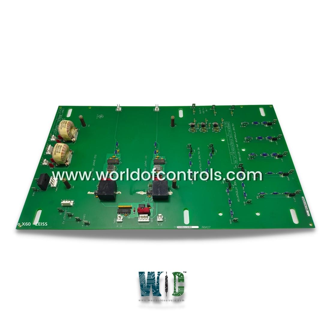
DS200SHVIG1BHD - SCR High Voltage Interface Board is available in stock which ships the same day.
DS200SHVIG1BHD - SCR High Voltage Interface Board comes in UNUSED as well as REBUILT condition.
To avail our best deals for DS200SHVIG1BHD - SCR High Voltage Interface Board, contact us and we will get back to you within 24 hours.
SPECIFICATIONS:
Part Number: DS200SHVIG1BHD
Manufacturer: General Electric
Series: Mark V
Product Type: SCR High Voltage Interface Board
Power Requirements: +5 V dc, 6 A
Input Voltage: 480VAC
Number of relay channels: 12
Power supply voltage: 24 V dc
Isolation Voltage: 1500VAC
Power System Frequency: 60Hz
Mounting: DIN-rail mounting
Technology: Surface mount
Operating temperature: -10 to +50°C
Communication Interfaces: RS-485, Ethernet
Size: 15.9 cm high x 17.8 cm
Repair: 3-7 Day
Availability: In Stock
Country of Origin: United States
Manual: GEI-100160
FUNCTIONAL DESCRIPTION:
DS200SHVIG1BHD is an SCR High Voltage Interface Board manufactured and designed by General Electric as part of the Mark V Series used in GE Drive Control Systems. The SHVI board provides an interface for signals from the drive’s SCR bridge to the drive’s power supply and instrumentation card and the DS200PCCA Power Connect Card (PCCA). The DS2OOSHVZ portion is the base number that identifies the printed wiring board, in this case, the SCR High Voltage Interface Board. The G# identifies a group, which is a variation of a particular board. The r and u digits are alphabetic characters that indicate the board revision level. The r digit reflects a functional change that is not downward compatible. It is essentially a new catalog number. The u digits represent revision levels that are downward compatible with the r revision level. The SHVI performs the following functions:
WOC maintains the largest inventory of Replacement Parts for GE Drive Control systems. Additionally, we offer warranty-backed unused and rebuilt boards as well as board repairs for your damaged ones. Our team of professionals is available around the clock for your OEM needs. We at WOC are happy to help you with any needs you may have in terms of automation. Please get in touch with our team by phone or email for pricing and availability on any components and repairs.
What are the main components of a drive control system?
The main components include motor drives (inverters or VFDs), controllers (PLCs, microcontrollers), sensors (encoders, resolvers), power supplies, communication interfaces, and human-machine interfaces (HMI).
What are the advantages of using drive control systems?
Drive control systems offer precise control over motor operation, leading to improved efficiency, energy savings, reduced wear and tear, enhanced productivity, and better performance in various industrial, commercial, and residential applications.
How do drive control systems work?
Drive control systems regulate the electrical power supplied to the motor based on feedback from sensors, control algorithms, and user-defined setpoints. They adjust parameters such as voltage, frequency, and current to achieve the desired speed, torque, or position control.