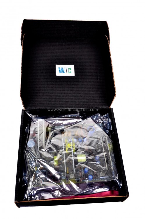
SPECIFICATIONS
Part No.: DS200SDCIG2AFB
Manufacturer: General Electric
Country of Manufacture: United States of America (USA)
Temperature: 0 to 60 oC
Product Type: DC Power Supply Board
Availability: In Stock
Series: Drive Control
Functional Description
DS200SDCIG2AFB is a DC Power Supply Board developed by GE. It is a part of Drive Control system. The board provides essential circuitry to instrument DC motor signals and AC lines. Specifically designed for use with external exciters, this board accommodates input voltages of up to 600 VAC, making it versatile and adaptable to a range of power systems. The board's primary function is to deliver logic power functions and interface circuitry, contributing to the overall control and operation of the DC2000 drives.
Features
- Within the board, a multitude of circuits are integrated to facilitate various functions. These circuits include, but are not limited to, driver circuits designed for armature Silicon Controller Rectifier (SCR) gating. Additionally, motor field power circuits are provided, excluding use with an SCR module. For applications requiring external circuits, the G2 group variation of the board is equipped with the necessary features.
- When removing the board, a crucial step is to meticulously disconnect all cables before initiating the removal process. This ensures a smooth transition and minimizes the risk of damage to connectors or other components. In the event of replacement with another board, it is imperative to reconnect all cables exactly as they were on the original, maintaining the correct configuration for seamless integration.
- The driver circuits are specifically tailored for armature SCR gating, playing a pivotal role in controlling and regulating the DC motor operation. These circuits contribute to the precision and efficiency of the armature SCR gating process.
- Users should exercise caution with the user-configurable jumpers on the board, as they are susceptible to damage. In the event of damage, prompt repairs are necessary to ensure that the board continues to operate seamlessly within the Mark V system without inhibiting its true functionality.
Contactor Drive Circuits
- The Contactor Drive Circuits on the board are integral components responsible for orchestrating the operation of the MA (Motor Armature) or MD (Motor Field) contactors within the DC2000 drive system. A key element in this control scheme is relay K2, strategically positioned as a pilot relay to interface with either the MA or MD contactor.
- Relay K2's role as a pilot relay involves responding to control signals. The component, serving as the central control unit, directs the activation of the relay K2 coil through dedicated connections, namely IPL-34 and IPL-35 C on the board. This intricate coordination ensures precise and timely engagement or disengagement of the MA or MD contactor, aligning with the operational requirements of the DC2000 drive system.
- In addition to relay K2, the board incorporates specific connectors and jumpers to fine-tune the control parameters:
- Connector CNPL: Connector CNPL assumes a pivotal role by providing a robust 115 V ac power supply to the MA contactor. This connector establishes a reliable electrical link, facilitating the necessary energy for the efficient operation of the MA contactor.
- Connector MACPL: Dedicated to the MD contactor driver, connector MACPL plays a crucial role by delivering a precise 24 V dc Field-Effect Transistor (FET) output. This output acts as a control signal for the MD contactor, enabling seamless coordination between the control board and the motor field circuit.
- Jumper JP1: Jumper JP1 introduces an element of versatility by providing the option to select whether the MD contactor operates independently of the MA contactor. The SDCC MCP (Motor Control Processor) exercises control over this configuration, allowing users to tailor the operational strategy based on specific system requirements.
- Jumper JP2: Jumper JP2 offers an adjustable parameter, allowing users to select the dropout time for the MA contactor. This customization is crucial for optimizing the response of the MA contactor, ensuring smooth transitions and operational efficiency.
- The meticulous integration of relay K2, connectors CNPL and MACPL, as well as jumpers JP1 and JP2 contribute to the overall reliability, adaptability, and precision of the contactor drive circuits, enhancing the performance of the DC2000 drive system.
The WOC team is always available to help you with your Drive Control requirements. For more information, please contact WOC.
Frequently Asked Questions
What is DS200SDCIG2AFB?
It is a DC Power Supply Board developed by GE under the Drive Control series.
What is the purpose of the delayed firing power circuit on the board?
The delayed firing power circuit serves the crucial function of providing power to the SCR (Silicon Controlled Rectifier) bridge gate-pulse transformer outputs. This circuit is designed with a delay mechanism to ensure that power remains off until the specific gating operation is required.
How does the delayed firing power circuit contribute to protection mechanisms?
The delayed firing power circuit acts as a protective feature by withholding power until the precise moment when gating is necessary. This precautionary measure ensures controlled and intentional activation, minimizing the risk of undesired or premature power supply to the SCR bridge gate-pulse transformer outputs.
What additional protection does the circuit offer in case of a failure?
As an added layer of protection, the delayed firing power circuit on the board includes a mechanism to remove gate firing power in the event of a failure. This proactive safety measure helps prevent potential issues or damage that may arise due to a failure, maintaining the integrity of the SCR bridge gate-pulse transformer outputs.
