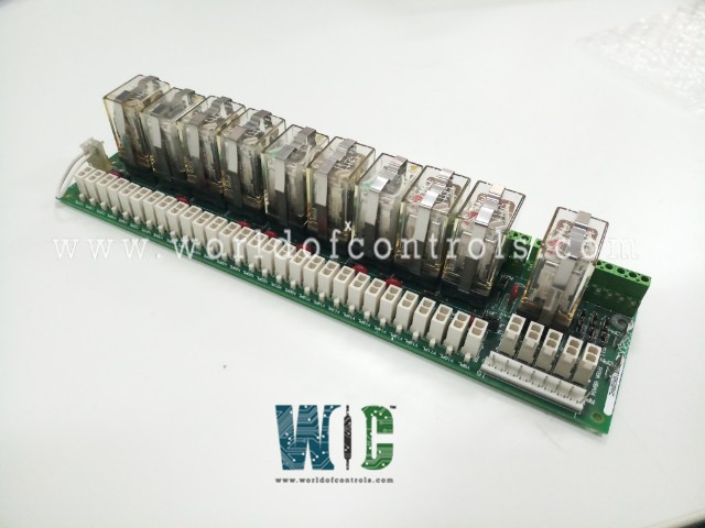
SPECIFICATIONS
Part No.: DS200RTBAG2ADB
Manufacturer: General Electric
Country of Manufacture: United States of America (USA)
Temperature: 0 to 60 oC
Manual: GEI-100161
Product Type: Relay Terminal Board
Availability: In Stock
Series: EX2000
Functional Description
DS200RTBAG2ADB is a Relay Terminal Board developed by GE. It is a part of EX2000 excitation system. It serves as an optional yet integral component situated within the drive or exciter cabinet, playing a pivotal role in the control and management of relay operations. The board is strategically positioned within the drive or exciter cabinet, optimizing its accessibility and integration within the broader control system architecture. Its placement ensures efficient relay operations and facilitates ease of maintenance and servicing when necessary.
Features
- Relay Configuration: The board boasts a total of ten relays, offering versatile control capabilities tailored to specific operational requirements. These relays can be driven either directly from the pilot relays on the LAN I/O Terminal Board (LTB) or remotely by the user, providing flexibility in relay management and control.
- Relay Types and Contacts:Among the ten relays provided by the board, seven feature two Form C contacts each, commonly known as DPDT relays. These relays offer multiple switching configurations, enhancing their versatility and adaptability to diverse control scenarios. Additionally, three relays are equipped with four Form C contacts each, denoted as 4PDT relays. These relays offer even greater switching capabilities, allowing for more complex control operations and configurations as needed.
- Control Options: The board provides users with multiple options for controlling relay operations. Relays can be driven directly from the pilot relays on the 531X307LTB LAN I/O Terminal Board, facilitating seamless integration within the control network. Alternatively, users can opt to control relays remotely, offering greater flexibility and customization in relay management based on specific operational requirements and preferences.
- Versatile Applications: With its diverse relay configurations and control options, the board finds application across various industries and systems, including power generation, industrial automation, and process control. Its ability to handle different types of loads and switching requirements makes it a valuable asset in optimizing system performance and enhancing operational efficiency.
Board Replacement Procedure
- Power Off the Drive: Before beginning any maintenance procedure, it's crucial to turn off the power to the drive. This ensures safety by eliminating the risk of electrical shock or damage to components during the maintenance process.
- Access the Board: Open the cabinet door of the drive to access the board. Typically, the board is situated below the drive's board rack. Accessing the board provides clear visibility and easy reach to the relays that require replacement.
- Remove Retaining Clip: Identify the retaining clip for the relay that needs replacement. Press on the top of the retaining clip while simultaneously pulling on either side of the clip to release it. This action disengages the clip from the relay socket, allowing for easy removal.
- Remove Old Relay: Once the retaining clip is removed, carefully pull the old relay straight out of the relay socket. Take care to handle the relay gently to avoid damage to the components or surrounding circuitry.
- Install New Relay: Orient the new relay correctly on the socket, ensuring it fits snugly and securely. Relays typically only fit one way due to their specific design. Press the new relay firmly into the seated position in the socket to establish proper electrical connections.
- Replace Retaining Clip: Position the retaining clip over the new relay, ensuring it is centered and aligned correctly. Press down on the top of the clip until the bottom of the clip engages securely in the relay socket. This ensures the relay is firmly held in place and prevents accidental dislodging during operation.
The WOC team is always available to help you with your EX2000 requirements. For more information, please contact WOC.
Frequently Asked Questions
What is DS200RTBAG2ADB?
It is a Relay Terminal Board developed by GE under the EX2000 series.
What are the Berg-type hardware jumpers on the board?
The Berg-type hardware jumpers are manually movable components on the board, crucial for configuring its operation. These jumpers, identified by a JP nomenclature, must be set correctly for the specific application requirements.
Are the jumper selections preconfigured or adjustable?
Most of the jumper selections on the board are factory set, meaning they come preconfigured from the manufacturer. However, they can be adjusted if necessary to accommodate specific application needs.
How can I ensure the jumpers are set correctly for my application?
The data sheets supplied with each controller, typically found in the drive or exciter cabinet door pocket, provide detailed information about the factory-set jumper positions. Consult these data sheets to verify that the jumpers are configured appropriately for your application.
