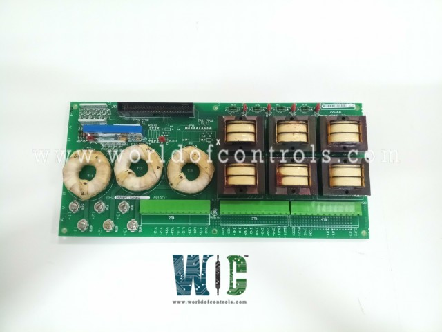
DS200PTCTG2BAA - Signal Conditioner Board

DS200PTCTG2BAA - Signal Conditioner Board DS200PTCTG2BAA - Signal Conditioner Board

World Of Controls understands the criticality of your requirement and works towards reducing the lead time as much as possible.

DS200PTCTG2BAA - Signal Conditioner Board is available in stock which ships the same day.

DS200PTCTG2BAA - Signal Conditioner Board comes in UNUSED as well as REBUILT condition.

To avail our best deals for DS200PTCTG2BAA - Signal Conditioner Board, contact us and we will get back to you within 24 hours.

SPECIFICATIONS

Part No.: DS200PTCTG2BAA
Manufacturer: General Electric
Country of Manufacture: United States of America (USA)
Temperature: 0 to 60 °C
Product Type: Signal Conditioner Board
Availability: In Stock
Series: EX2000

Functional Description

DS200PTCTG2BAA is a Signal Conditioner Board developed by GE. It is a part of EX2000 system. PTCT board serves as a vital component within a broader system, playing a key role in isolating and scaling voltage and current signals sourced from Potential Transformers (PTs) and Current Transformers (CTs). Its primary function is to ensure accurate and reliable measurements of electrical parameters while providing additional functionality through auxiliary inputs and outputs.

Features

  • One of the crucial tasks undertaken by the board is the isolation and scaling of voltage and current signals derived from PTs and CTs. This process is essential for maintaining the integrity and accuracy of the signals throughout the system. By isolating these signals, the board prevents interference and ensures that the measurements are representative of the actual electrical parameters in the system.
  • In addition to isolation and scaling, the board is designed to accommodate auxiliary inputs and outputs. These auxiliary channels can handle signals of either low voltage (e.g., below 10 V dc) or 4-20 mA current signals. This flexibility in handling various types of signals enhances the versatility of the PTCT board, making it adaptable to different operational requirements.
  • The PTCT board's role in isolating and scaling voltage and current signals is particularly crucial for ensuring the safety and accuracy of downstream components in the electrical system. By providing a controlled and scaled representation of these signals, the board contributes to the overall precision of the measurements and ensures that the information fed into the system is reliable.
  • Specifically, the U1 component on the PTCT board is dedicated to providing an isolated input circuitry. This feature further emphasizes the commitment to maintaining signal integrity by preventing unwanted interactions between different parts of the system. Isolated input circuitry ensures that signals are accurately measured without being influenced by external factors, enhancing the overall performance and reliability within the broader electrical infrastructure.

Voltage Signals

  • The board is intricately designed to handle voltage signals with precision and reliability. At its core are six high precision transformers, each engineered with a secondary rating of 1.6 Vrms at a primary nominal rating of 120 Vrms. This configuration ensures accurate transformation and scaling of the incoming voltage signals, allowing for meticulous measurements within the electrical system.
  • The transformers on the PTCT play a pivotal role in converting the primary voltage signals to a standardized and manageable level for further processing. The choice of high precision transformers underscores the board's commitment to maintaining accuracy and consistency in the measurements taken from the electrical system.
  • To facilitate seamless integration and connection, the board provides separate terminal points for each primary connection. This thoughtful design not only simplifies the installation process but also ensures that each connection point is dedicated to a specific transformer, minimizing the risk of cross-interference and optimizing the overall performance of the board.
  • For the convenience of technicians and engineers conducting measurements or diagnostic checks, the board incorporates testpoints, labeled TPl through TP12. These testpoints serve as designated locations for measuring the voltage signals. By providing specific testpoints, the board enhances accessibility and streamlines the testing process, enabling efficient troubleshooting and maintenance procedures.
  • The utilization of 1.6 Vrms secondary rating at 120 Vrms primary nominal rating in the transformer design aligns with industry standards, ensuring compatibility with a wide range of electrical systems. This standardized approach not only facilitates interoperability but also enhances the versatility of the board, making it suitable for various applications and environments.


Current Signals

  • The PTCT board is engineered to not only handle voltage signals but also to accurately and efficiently manage current signals within the electrical system. This capability is made possible through the incorporation of three Current Transformers (CTs) and the strategic placement of a burden resistor across the secondary winding of each CT.
  • Each CT on the board is meticulously designed to interface with the electrical system, providing a secondary signal that is proportional to the primary current passing through the system. The burden resistor, situated across the CT's secondary winding, plays a crucial role in shaping the characteristics of the current signal, ensuring that it can be precisely measured and processed by downstream components.
  • To facilitate streamlined connections and prevent cross-interference, the board provides separate terminal points for each primary connection associated with the CTs. This modular design not only simplifies installation but also ensures that each CT is dedicated to its specific connection point, optimizing the accuracy of current measurements.
  • Testpoints TP13 through TP18 are strategically positioned to enable technicians and engineers to measure the voltage across the burden resistors labeled R10 through R12. These testpoints serve as designated locations for diagnostic checks and measurements, providing insights into the characteristics of the current signals passing through the CTs.
  • The use of burden resistors in conjunction with the CTs is a critical aspect of the design. These resistors not only shape the current signal but also provide a known impedance against which the voltage drop can be measured. This measured voltage is indicative of the current passing through the CT, allowing for accurate quantification and analysis of the electrical system's current flow.
  • The strategic placement of testpoints for measuring the voltage across burden resistors exemplifies the commitment to providing a user-friendly interface for technicians. This feature enhances the diagnostic capabilities of the board, allowing for efficient troubleshooting and maintenance procedures.

Board Replacement Procedure

  • Power off the exciter to ensure a safe replacement process.
  • Carefully disconnect all cables from the PTCT board:
    • For ribbon cables, place one hand on each side of the cable connector that mates with the board connector. Gently pull the cable connector with both hands.
    • For cables with pull tabs, carefully pull the tab.
  • Remove the screws securing the board, located on the top and bottom.
  • On the new replacement board, configure all adjustable settings to match exactly with those on the board being replaced (old board).
  • Install the new board into the rack and secure it in place by replacing the mounting screws.
  • The cables are labeled with the correct connector names, corresponding to the markings on the board. Reconnect all cables as labeled, ensuring that they are properly seated at both ends. This step is crucial to maintain proper connectivity and functionality after replacement.

The WOC team is always available to help you with your EX2000 requirements. For more information, please contact WOC.

Frequently Asked Questions

What is DS200PTCTG2BAA?
It is a Signal Conditioner Board developed by GE under the EX2000 series.

What is the core component of the board for managing voltage signals?
At the core are six high precision transformers, each engineered with a secondary rating of 1.6 Vrms at a primary nominal rating of 120 Vrms.

How does the configuration of the transformers ensure accuracy in measurements?
This configuration ensures accurate transformation and scaling of incoming voltage signals, allowing for meticulous measurements within the electrical system.

What role do the transformers play in the conversion of voltage signals?
The transformers on the board play a pivotal role in converting primary voltage signals to a standardized and manageable level for further processing.

Why is the use of high precision transformers significant?
The choice of high precision transformers underscores the board's commitment to maintaining accuracy and consistency in the measurements taken from the electrical system.