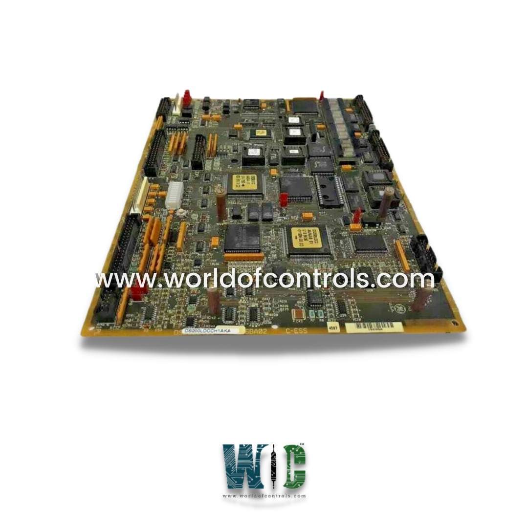
DS200LDCCH1AHA - Drive Control/LAN Communications Board

DS200LDCCH1AHA - Drive Control/LAN Communications Board DS200LDCCH1AHA - Drive Control/LAN Communications Board

World Of Controls understands the criticality of your requirement and works towards reducing the lead time as much as possible.

DS200LDCCH1AHA - Drive Control/LAN Communications Board is available in stock which ships the same day.

DS200LDCCH1AHA - Drive Control/LAN Communications Board comes in UNUSED as well as REBUILT condition.

To avail our best deals for DS200LDCCH1AHA - Drive Control/LAN Communications Board, contact us and we will get back to you within 24 hours.

SPECIFICATIONS

Part Number: DS200LDCCH1AHA
Manufacturer: General Electric
Series: Drive Control
Product Type: Drive Control/LAN Communications Board
Operating Temperature 0 to 60oC (32 to 149 oF)
Availability: In Stock
Country of Manufacturer: United States (USA)

Functional Description

DS200LDCCH1AHA is a Drive Control/LAN Communications Board developed by General Electric. It is a part of Drive Control system. The Drive Control/LAN Communications board (LDCC) is an component designed to control and communication functionalities for GE's DIRECTO-MATIC 2000 family of drives and exciters. The board utilizes advanced microprocessor technology to oversee and process various drive, motor, and customer I/O functions. This includes tasks such as speed control, torque regulation, and monitoring of input/output signals, ensuring precise and efficient operation of the drive system.

Features

  • Local Area Network (LAN) Communications Control: In addition to drive and I/O control, the board manages local area network (LAN) communications for drive I/O. It serves as the central hub for facilitating communication between different components of the drive system, enabling seamless data exchange and coordination.
  • Application Software and Configuration Data Handling: Stores and executes application software tailored for the specific requirements of the drive system. It also manages customer-specific configuration data, allowing for customized settings and parameters to be applied to the drive based on unique operational needs.
  • Onboard Operator Interface for Software Adjustments and Diagnostics: Featuring an onboard operator interface, provides users with the ability to make software adjustments and conduct diagnostic testing directly from the board itself. This interface streamlines the process of fine-tuning drive parameters and troubleshooting issues, enhancing operational efficiency and system maintenance.
  • Hardware and Software Drive Reset Functions: Incorporates both hardware and software-based drive reset functions, enabling users to perform system resets as needed. These functions help restore the drive system to a predefined state, addressing errors or malfunctions and minimizing downtime.

Software features

  • Storage in Memory Chips: The board stores its onboard software in memory chips, ensuring quick access to essential program instructions and data during operation. These memory chips are carefully selected to provide reliable and efficient storage for the software components.
  • Flash PROMs for Configuration Data: Six flash Programmable Read-Only Memory (PROM) chips, labeled U6, U7, U11, U12, U22, and U23, contain configuration data essential for drive operation. These PROMs are pre-programmed with configuration settings at the factory but offer the flexibility to be reprogrammed in the field if necessary. This allows for customization and adjustment of drive parameters to suit specific application requirements.
  • EEPROM for Field-Adjustable Parameters: An Electrically Erasable Programmable Read-Only Memory (EEPROM) chip, labeled U9, holds field-adjustable parameters that can be modified as needed. Unlike the configuration data stored in the flash PROMs, these parameters are intended for fine-tuning and adjustment during field commissioning or maintenance activities.
  • Reprogramming Capabilities: While the configuration data stored in the flash PROMs is initially programmed at the factory, the board supports reprogramming in the field if required. This capability allows for updates or modifications to the configuration settings without the need for board replacement, offering flexibility and adaptability to changing operational needs.
  • Downloadable Field-Adjustable Parameters: The field-adjustable parameters stored in the EEPROM can be downloaded using dedicated drive configuration tools. This process enables users to access and modify parameters such as speed, torque, and control settings, ensuring optimal performance and customization of the drive system to specific application requirements.

Operator Interface

  • 16-Character Digital Display: Equipped with a 16-character digital display that provides essential visual feedback to the operator. This display serves as a primary means of conveying information such as system status, diagnostic messages, and parameter values, enhancing user awareness and facilitating troubleshooting.
  • Connector KPPL for Optional Operator Interface Module: Connector KPPL on the board serves as the interface for connecting an optional operator interface module, known as the Programmer. This modular approach allows users to expand the functionality by adding the Programmer module as needed, providing additional capabilities for user interaction.
  • Programmer Module (Optional): The Programmer module is an optional accessory that enhances the operator interface of the board. It consists of an alphanumeric keypad and a display window, offering intuitive controls and visual feedback for software adjustments and diagnostic testing.
    With the Programmer module installed, users gain access to advanced functionality for configuring drive parameters, performing diagnostic tests, and accessing system status information in a user-friendly manner.
  • Software Adjustments and Diagnostic Testing: The operator interface, whether through the built-in 16-character digital display or the optional Programmer module, allows users to perform software adjustments and diagnostic testing conveniently. Users can interact with the interface to modify drive settings, adjust operational parameters, and conduct diagnostic tests to ensure optimal performance and troubleshoot any issues that may arise during operation.
  • Enhanced User Experience: By incorporating an intuitive operator interface, the LDCC board enhances the overall user experience, enabling operators and maintenance personnel to interact with the drive system effectively. The availability of visual feedback and user-friendly controls simplifies the process of configuring drive parameters and diagnosing system faults, contributing to improved efficiency and productivity.

WOC has the largest stock of Speedtronic control spares. Please contact our staff by phone or email for pricing and availability on any parts and repairs

FREQUENTLY ASKED QUESTIONS

What is DS200LDCCH1AHA?
It is a Drive Control/LAN Communications Board developed by General Electrics.

What is the purpose of the operator interface?
The operator interface allows users to interact with the board, enabling software adjustments and diagnostic testing for the drive system.

What components make up the operator interface?
The operator interface includes a 16-character digital display as well as an optional Programmer module, which consists of an alphanumeric keypad and display window.

How does the 16-character digital display benefit users?
The digital display provides essential visual feedback, conveying system status, diagnostic messages, and parameter values to the operator, enhancing user awareness and facilitating troubleshooting.

What is the purpose of connector KPPL?
Connector KPPL serves as the interface for connecting the optional Programmer module, allowing users to expand the functionality with additional controls and display capabilities.