World Of Controls understands the criticality of your requirement and works towards reducing the lead time as much as possible.
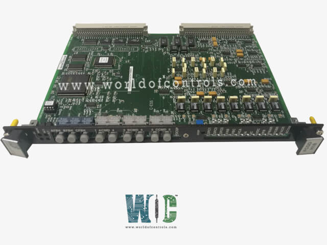
DS200FCGDH1BAA - Gate Distribution and Status Card is available in stock which ships the same day.
DS200FCGDH1BAA - Gate Distribution and Status Card comes in UNUSED as well as REBUILT condition.
To avail our best deals for DS200FCGDH1BAA - Gate Distribution and Status Card, contact us and we will get back to you within 24 hours.
Part No.: DS200FCGDH1BAA
Manufacturer: General Electric
Country of Manufacture: United States of America (USA)
Product Type: Gate Distribution and Status Card
Availability: In Stock
Series: LCI
DS200FCGDH1BAA is a Gate Distribution and Status Card developed by GE. It is a part of its LCI (Load Commutated Inverter) series. This interface board plays a crucial role in managing the operation of 6-pulse, phase-controlled, non-reversing bridges. It integrates advanced functionality to ensure precise control, monitoring, and diagnostics in industrial applications.
The system reset signal plays a vital role in initializing the board's operation. During power-up or a hardware reset, this signal resets all registers on the board to their default initial values. By doing so, the system ensures it starts from a known, stable state, avoiding potential issues caused by residual data or errors from prior operations. This feature is crucial for maintaining reliability and consistency in industrial environments where the board operates as part of a critical system.
The system heartbeat serves as a periodic signal generated by an electronic component to confirm its operational status. This functionality is supported by the heartbeat register on the FCGD board.
If the count in the heartbeat register exceeds its design limit (typically 8 milliseconds), the system triggers a safety response:
A hard reset is required to clear this condition, ensuring system integrity before resuming functionality.
The FCGD board uses fiber-optic firing signal transmitters to control the gating of six cell strings in a bridge. This process is governed by the firing mask register, which contains six entries corresponding to the six cell strings.
The WOC team is always available to help you with your LCI requirements. For more information, please contact WOC.
What is DS200FCGDH1BAA?
It is a Gate Distribution and Status Card developed by GE under the LCI series.
What is the function of the System Reset signal?
The System Reset signal initializes all the board's registers to their default values during power-up or hardware resets. This ensures the system starts from a stable, known state, preventing errors from prior operations.
What is the System Heartbeat, and why is it important?
The System Heartbeat is a periodic signal generated by the board to confirm that its components are operational. The heartbeat register begins counting when the VME host CPU writes to it for the first time. A green LED labeled IMOK (I am okay) lights up to indicate the board's health. If the count in the heartbeat register exceeds its limit (e.g., 8 milliseconds), the LED turns off, and gating stops, requiring a hard reset to restore functionality.
What happens if the System Heartbeat fails?
If the System Heartbeat exceeds its design limit The IMOK LED turns off. The gating signals are disabled to prevent unsafe operations. A hard reset is required to resume normal operations.