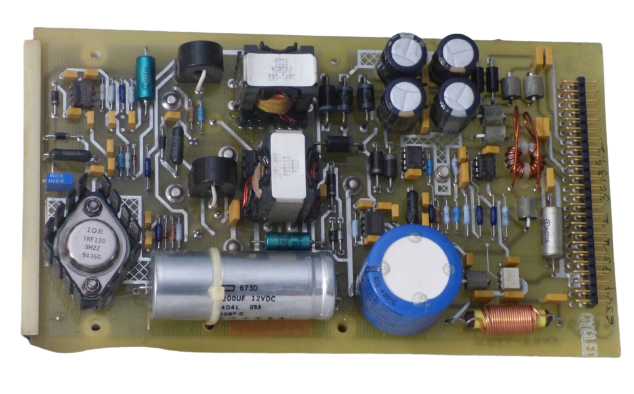
World Of Controls understands the criticality of your requirement and works towards reducing the lead time as much as possible.
5462-750 - Secondary Power Supply Module is available in stock which ships the same day.
5462-750 - Secondary Power Supply Module comes in UNUSED as well as REBUILT condition.
To avail our best deals for 5462-750 - Secondary Power Supply Module, contact us and we will get back to you within 24 hours.
Part Number: 5462-750
Manufacturer: Woodward
Product type: Secondary Power Supply Module
Input Voltage: 24 Vdc ±10%
Output Voltage: 5 Vdc ±5%
Output Current: 10 A maximum
Repair: 3-7 Day
Availability: In Stock
Country of Manufacture: United States (USA)
5462-750 is a Secondary Power Supply Module developed by Woodward. In the event of a primary power source failure or any other power-related issues, this module seamlessly takes over and supplies the necessary power to ensure uninterrupted operation. This feature is crucial in maintaining the stability and reliability of the gas turbine control system, safeguarding it against potential disruptions and failures. The Secondary Power Supply Module incorporates advanced features and safety mechanisms. It incorporates monitoring and diagnostic capabilities to detect and report any abnormalities or faults promptly. The module's seamless integration into the gas turbine control system architecture simplifies installation and maintenance procedures.
World of Controls has the most comprehensive selection of GE and Woodward components. Our professionals are available to help you with your requirements at any time. If you require any additional information, please contact WOC immediately.
What is 5462-750?
It is Secondary Power Supply Module developed by Woodward.
How do I check the status of the Kernel Power Supply?
Ensure that all of the Kernel Power Supply's red fault LEDs are turned off. If any of the LEDs are illuminated, refer to Section 4.8 for Kernel Power Supply Troubleshooting.
What steps should I follow for CPU 040 configuration?
Toggle two of the CPU's RESET switches up briefly before returning them to their normal down position. Toggle the remaining CPU RESET switch to the up position, then back to the down position. When all CPUs have synchronized and completed their tests, there should be no red LEDs on the CPU modules or I/O modules, and the control will begin running the application program.