World Of Controls understands the criticality of your requirement and works towards reducing the lead time as much as possible.
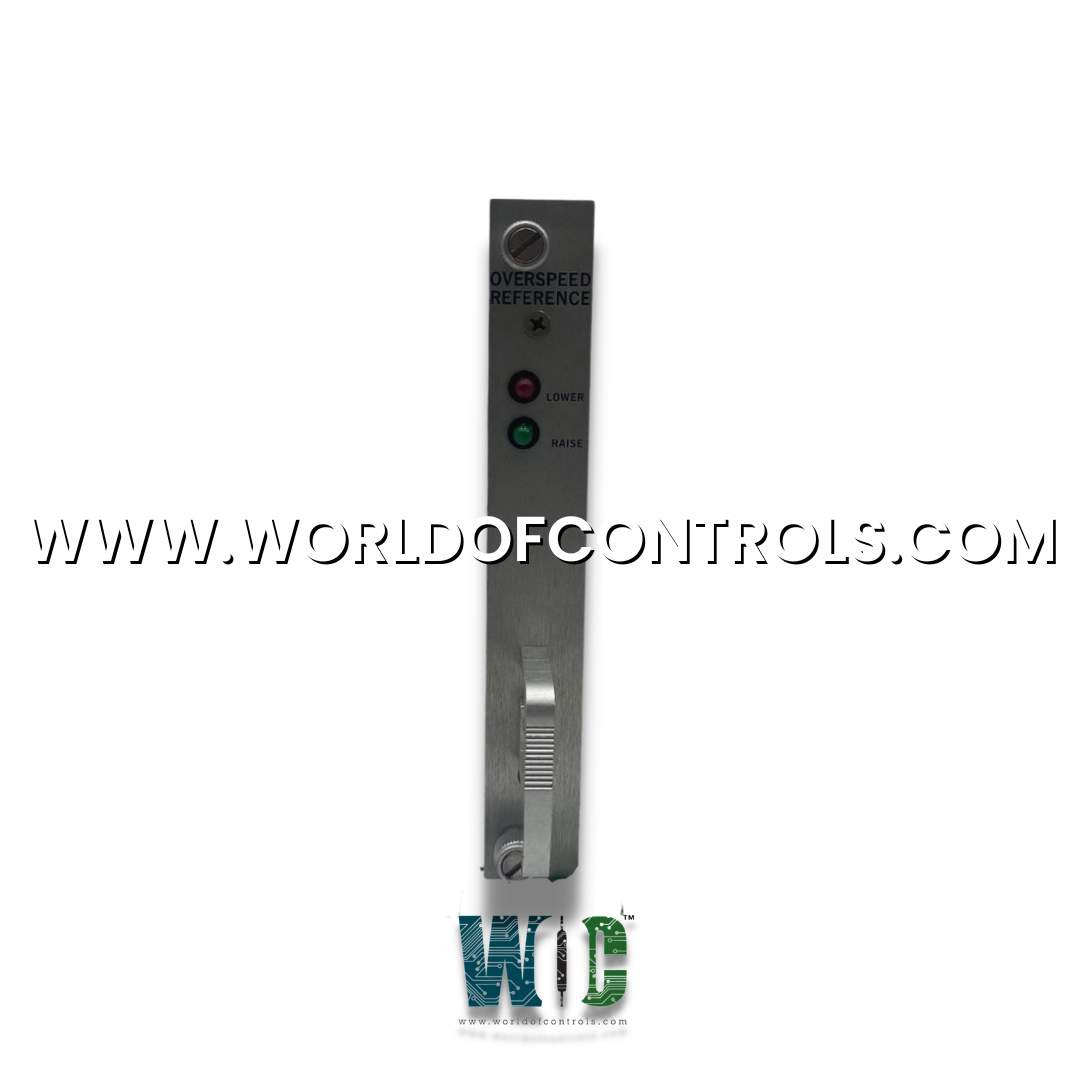
5432-271 - Overspeed Reference Control Module is available in stock which ships the same day.
5432-271 - Overspeed Reference Control Module comes in UNUSED as well as REBUILT condition.
To avail our best deals for 5432-271 - Overspeed Reference Control Module, contact us and we will get back to you within 24 hours.
SPECIFICATIONS:
Part Number: 5432-271
Manufacturer: Woodward
Operating Voltage: 24V DC / 110V-240V AC
Speed Measurement Accuracy: � 0.1%
Speed Range: 0 to 15,000 RPM
Threshold Range: 100 RPM
Response Time: < 50 ms
Temperature Range: -20�C to +70�C
Weight: 0.5 kg
Product type: Overspeed Reference Control Module
Country of Manufacture: United States
FUNCTIONAL DESCRIPTION:
5432-271 is an Opto Isolator Module manufactured and designed by Woodward as part of the 5400 Series used in Turbine Control Systems. The Overspeed Reference Control Module is a critical component used in industrial machinery and turbine control systems to monitor and manage rotational speed. Its main function is to detect when the speed of a rotating machine, such as a gas turbine, steam turbine, generator, or compressor, exceeds safe operational limits, a condition known as overspeed. When overspeed is detected, the module initiates protective actions to prevent equipment damage, system failure, or safety hazards. These actions may include activating alarms, triggering shutdown mechanisms, or sending signals to the control system to reduce the speed. Key features often include:
The module is typically mounted on a DIN rail or control panel in a location free from excessive vibration, dust, and moisture. It should be installed in a position that allows easy access for wiring and future maintenance. Electrical installation begins with connecting the module to its rated power supply, typically 24V DC or 110�240V AC, ensuring proper polarity and grounding.
Speed sensors are then mounted on the rotating parts of the machine and connected to the input terminals of the module. Proper alignment and secure mounting of these sensors are critical for accurate speed measurements. Once the sensors are in place, the output terminals of the module are wired to control relays, actuators, or safety interlocks that will execute shutdown or alarm actions in case of an overspeed condition. After wiring, the overspeed threshold is configured either via onboard settings or through a dedicated software interface, depending on the model.
WOC has the most extensive stock of OEM Replacement Parts for Woodward Control Systems. We can also repair your faulty boards and supply unused and rebuilt boards backed up with a warranty. Our team of experts is available around the clock to support your OEM needs. Our team of experts at WOC is happy to assist you with any of your automation requirements. For pricing and availability on parts and repairs, kindly contact our team by phone or email.
What are the input signal specifications for speed sensing?
Most modules accept inputs from magnetic pickups (MPUs) with signal ranges of 0.5�30 Vrms, frequencies from 1 Hz up to 20 kHz, and input impedance typically above 100 k Ohm.
What is the typical overspeed trip response time?
The overspeed trip signal is usually generated within 10�50 milliseconds after threshold detection, depending on the processing architecture and signal filtering.
How is the trip setpoint configured?
Trip points are set either via front-panel DIP switches, potentiometers, or digitally using configuration software over serial/USB/Modbus interfaces.