World Of Controls understands the criticality of your requirement and works towards reducing the lead time as much as possible.
5432-277 - Final Driver Circuit Board is available in stock which ships the same day.
5432-277 - Final Driver Circuit Board comes in UNUSED as well as REBUILT condition.
To avail our best deals for 5432-277 - Final Driver Circuit Board, contact us and we will get back to you within 24 hours.
TECHNICAL SPECIFICATIONS:
Part Number: 5432-277
Manufacturer: Woodward
Product Type: Final Driver Circuit Board
Functional Group: Driver / Actuator Control Module
Series: Woodward Custom / NetCon Platform Series
Application: High-Current Actuator & Valve Control
Driver Output Channels: High-Speed Actuator Driver Channels
Control Interface: Backplane Communication to System CPU
Operating Power Input: Dedicated DC Logic & Field Power Feed
Isolation: Galvanic & Optical Isolation
Diagnostic Features: Fault Feedback, Overcurrent Protection & Status Monitoring
Mounting Type: Plug-in Rack Module
Conformal Coating: Yes
System Compatibility: Woodward Control Systems
Availability: In Stock
Repair Lead Time: 3–7 Days
Country of Origin: United States
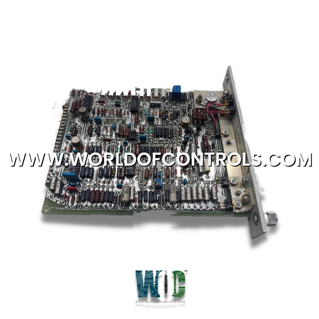
The Woodward 5432-277 is a Final Driver Circuit Board designed and manufactured by Woodward for industrial turbine control systems and governor assemblies. Serving as the output stage interface, the module translates low-level control signals from the central processing unit into high-current driver outputs required to actuate electro-hydraulic valves, servomotors, and fuel control actuators.
CLOSED-LOOP CURRENT REGULATION & ACTUATOR POSITIONING:
The Circuit Board operates as an active power driver stage, continuously adjusting current delivered to positioning actuators. Rather than acting as a simple switch, the board processes variable analog positioning commands from the central governor and uses closed-loop current feedback to maintain precise valve orifice openings despite changing coil resistance, operating temperatures, or hydraulic backpressure.
THERMAL SHUTDOWN RECOVERY & INDUCTIVE FLYBACK PROTECTION:
To handle the heavy inductive loads typical of large turbine valve coils, the Circuit Board integrates dedicated flyback diode networks and active energy dissipation circuits. These prevent back-EMF voltage spikes from damaging power MOSFETs during sudden load rejections or emergency trips. Onboard thermal sensors continuously evaluate driver stage dissipation, initiating controlled current foldback to safeguard the module without causing abrupt, nuisance trips.
WHY BUY FROM WOC
World of Controls maintains the industry's largest inventory of genuine OEM replacement components exclusively for GE Speedtronic control systems. To minimize critical plant downtime, we provide both UNUSED surplus and fully REBUILT circuit boards, processor cards, and I/O modules—each backed by comprehensive warranty protection. Every reconditioned Speedtronic component undergoes thorough diagnostic testing, circuit-level evaluation, and functional bench-testing by our experienced technical team before dispatch. In addition to direct parts supply, our facility offers complete diagnostic repair and unit exchange services with rapid turnaround times for your damaged GE Speedtronic hardware. Our dedicated team of automation specialists is available 24/7 to assist with technical selection, stock verification, and emergency component sourcing for your Speedtronic control panels. Contact us today via phone or email to request pricing, confirm live inventory, or discuss custom repair solutions for your GE Speedtronic infrastructure.
What is the Woodward 5432-277?
The Woodward 5432-277 is a Final Driver Circuit Board used in Woodward turbine control systems to drive and regulate high-current fuel actuators and electro-hydraulic valves. It functions as an output-stage interface between the control system and connected actuator loads. The board converts control commands into regulated electrical drive signals for actuator positioning.
How does the driver circuit regulate actuator current?
The driver circuit uses the commanded actuator signal to control the output delivered to the actuator coil. Current feedback can be used by the control circuitry to maintain the required drive level as electrical and load conditions change. Proper current regulation helps provide consistent actuator response during turbine operation.
What protection features are associated with the driver output stage?
The driver output stage is designed to handle inductive actuator loads and may incorporate protection against overcurrent and voltage transients. Flyback and energy-dissipation circuitry helps limit the effects of inductive voltage generated when actuator current changes rapidly. Thermal protection can also help prevent excessive stress on the output components.
How does the board communicate with the turbine control system?
The board interfaces with the control system through the system backplane and associated control electronics. Control commands are transferred from the processing section to the driver circuitry, which then produces the appropriate field output. Diagnostic or status feedback can be returned to the control system for monitoring.
What can cause an actuator connected to the driver board to respond incorrectly?
Incorrect actuator response can result from an open or shorted actuator coil, damaged field wiring, an incorrect control signal, power-supply problems, or faults within the driver circuitry. Excessive coil resistance or unstable feedback can also affect current regulation. Checking the actuator, wiring, supply voltage, command signal, and diagnostic indications can help isolate the source of the problem.
What should be checked if the driver output is missing?
First verify that the board is receiving the required operating power and that the control system is issuing the expected actuator command. Inspect the backplane connection, field wiring, actuator coil, and any available fault or status indications. If the external circuits are operating correctly but the output remains absent, the driver board should be tested for output-stage or component-level faults.