World Of Controls understands the criticality of your requirement and works towards reducing the lead time as much as possible.
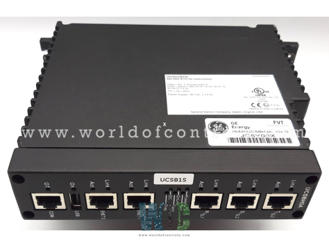
IS421UCSBH4A - Safety Controller Module is available in stock which ships the same day.
IS421UCSBH4A - Safety Controller Module comes in UNUSED as well as REBUILT condition.
To avail our best deals for IS421UCSBH4A - Safety Controller Module, contact us and we will get back to you within 24 hours.
Part Number: IS421UCSBH4A
Manufacturer: General Electric
Series: Mark VIe
Availability: In Stock
Microprocessor: 1066 MHz Intel EP80579
Operating System: QNX Neutrino
Power Requirements: UCSBH4A: 28.7 W peak, 17.3 W nominal
Weight: 1 Kg
Manual: GEH-6721
Country of Manufacture: United States (USA)
IS421UCSBH4A is a Safety Controller Module developed by GE. It is a part of Mark VIe control system. UCSB controllers represent stand-alone computing units specifically designed to execute application-specific control system logic. Unlike traditional controllers where I/O is integrated into a backplane, controllers operate without hosting any application I/O internally. Instead, all I/O networks are externally attached to each UCSB controller, ensuring they receive comprehensive input data for efficient control system operation.
The controller's hardware and software architecture is meticulously designed to guarantee the integrity of application input data. In scenarios where a controller undergoes maintenance or repair and is powered down, the architecture ensures that no single point of application input is lost. This robust design contributes to the system's reliability and resilience.
UCSB controllers are panel-mounted units that establish communication with I/O packs through on-board I/O network (IONet) interfaces. IONet is a private, special-purpose Ethernet designed exclusively to support Mark controls I/O modules and controllers. This dedicated network ensures secure and efficient communication within the control system.
The controller is equipped with application-specific software tailored to its designated function within the control system. This software allows the controller to execute either rungs or blocks, providing flexibility in control logic implementation.Supports online modifications to its control software, enabling minor adjustments without the need for system restarts. This feature enhances operational efficiency and facilitates real-time optimization in response to evolving system requirements.
To ensure precise synchronization within the control system, the UCSB controller leverages the IEEE 1588 protocol. This protocol is employed through the R, S, and T IONets to synchronize the clocks of both I/O packs and controllers. The synchronization achieved is remarkable, with a precision of within ±100 microseconds. This meticulous clock synchronization is critical for maintaining accurate timing in industrial processes, contributing to the overall reliability and precision of the control system.
The UCSB controller serves as a central hub for data transfer within the control system. Utilizing the R, S, and T IONets, external data seamlessly flows to and from the control system database housed in the controller. This comprehensive data exchange encompasses various elements, including process inputs and outputs to and from I/O modules. This bidirectional communication ensures that the control system remains well-informed about the state of the industrial processes it governs.
WOC is happy to assist you with any of your automation requirements. Please contact us by phone or email for pricing and availability on any parts and repairs.
What is IS421UCSBH4A?
It is a Safety Controller Module developed by GE.
What is the Mark VIeS Safety controller application code?
The application code refers to the specific set of instructions and logic implemented in the Mark VIeS Safety controller to govern its operation in a functional safety.
Why is Branding required when the Mark VIeS Safety controller application code is changed and downloaded?
Branding is required when the controller application code is changed and downloaded to ensure that any modifications are acknowledged and identified. This is a crucial aspect of functional safety protocols, as it helps maintain transparency and traceability in the system.
What triggers the need for Branding in the Mark VIeS Safety controller?
The need for Branding is triggered when changes are made to the Mark VIeS Safety controller application code and subsequently downloaded. This ensures that the system is aware of any alterations in the code, minimizing the risk of unintended consequences and ensuring compliance with functional safety requirements.
How does the Boot LED process during normal boot?
During a normal boot process, the Boot LED remains continuously lit. This indicates that the boot sequence is progressing without any detected errors.
What happens if an error is detected during the boot process?
If an error is detected during the boot process, the Boot LED transitions into a flashing mode. It flashes at a frequency of 1 Hz, being on for 500 ms and off for 500 ms. Following the flashing state, the LED turns off for three seconds before repeating the cycle. The number of flashes during the flashing state indicates the specific failed state.