World Of Controls understands the criticality of your requirement and works towards reducing the lead time as much as possible.
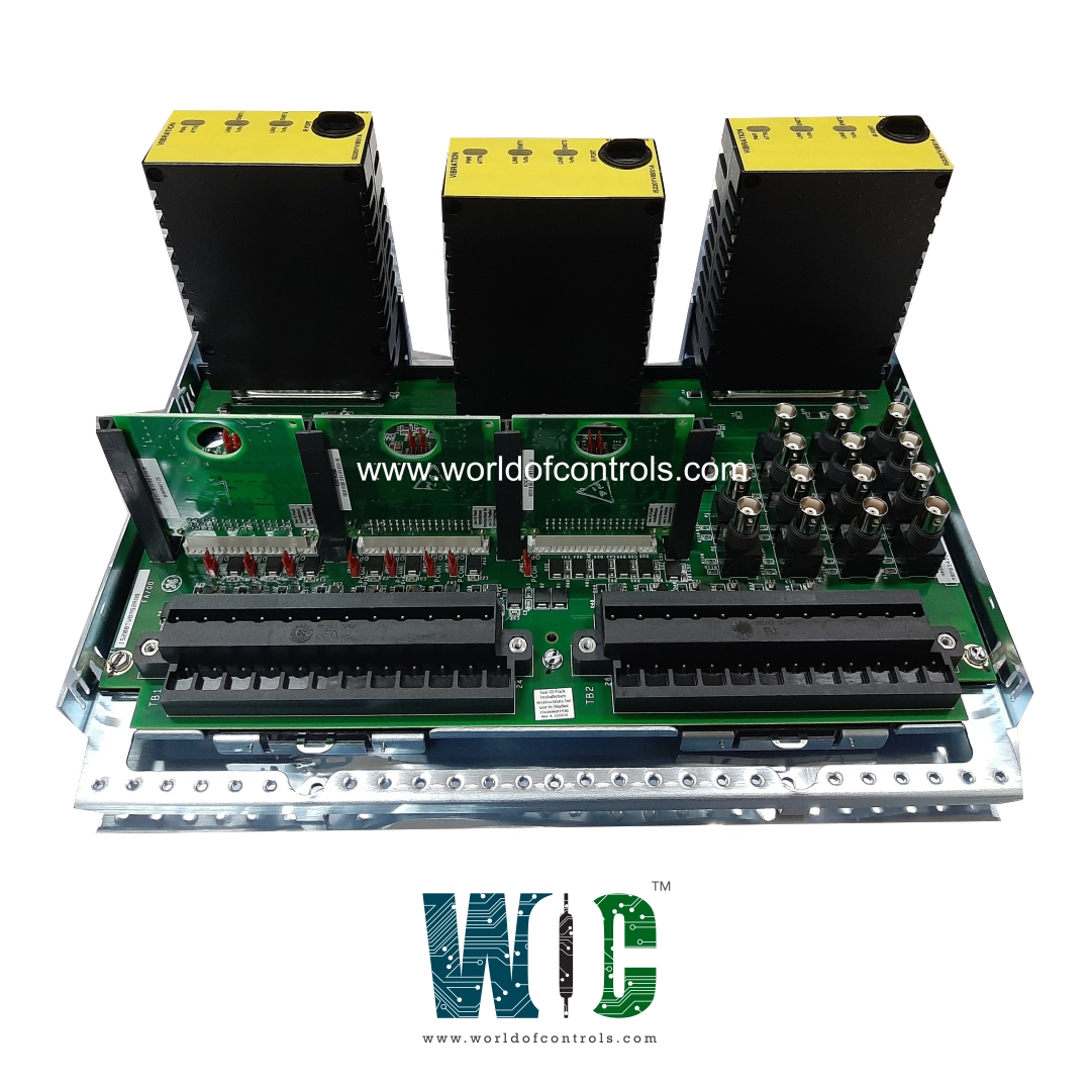
IS230TVBAH6A - Vibration Input Terminal Board is available in stock which ships the same day.
IS230TVBAH6A - Vibration Input Terminal Board comes in UNUSED as well as REBUILT condition.
To avail our best deals for IS230TVBAH6A - Vibration Input Terminal Board, contact us and we will get back to you within 24 hours.
SPECIFICATIONS:
Part Number: IS230TVBAH6A
Manufacturer: General Electric
Series: Mark VIe
Product Type: Vibration Input Terminal Board
Maximum Lead Resistance: 15Ω
Analog output current: 0-20 mA
N28 voltage: 28 normal
N28 ripple: 280 mV pk
Number of channels: 8
Number of buffered outputs: 14
N24 maximum current: 12mA
N28 maximum current: 400 mA
Operating temperature: -30 to 65 °C
Size: 10.16 cm wide x 33.02 cm
Technology: DIN-Rail
Repair: 3-7 Day
Availability: In Stock
Country of Origin: United States
Manual: GEH6721D
FUNCTIONAL DESCRIPTION:
IS230TVBAH6A is a Vibration Input Terminal Board manufactured and designed by General Electric as part of the Mark VIe Series used in GE Distributed Control Systems. The vibration terminal board (TVBA) acts as a signal interface board for the Mark VIe I/O pack PVIB. In the Mark VI system, the VVIB board works with TVIB. The TVBA provides a direct interface to seismic (velocity), Proximitors, Velomitors, and accelerometer-type probes. The terminal board provides signal suppression and electromagnetic interface (EMI) protection for each input signal. Signals are also connected to a pull-up bias to allow open circuit detection. The signals are passed on to the Mark VIe I/O packs through a 37-pin connector. The TVBA can be used for either simplex or TMR applications. TMR applications fan the signal to three I/O packs. The TVBA contains buffered outputs to additional connectors beyond the standard 37-pin connection. This feature allows special 9 and 25-pin connectors to feed the Bently Nevada® 3500 monitoring system. A bayonet nut connection (BNC) connection for each channel is also included with this feature, to feed other third-party monitoring equipment. Mark VIe systems do not use the traditional RKPS power supply.
INSTALLATION:
The TVBA accepts 14 sensor inputs that are wired directly to two I/O terminal blocks. Each block is held down with two screws and has 24 terminals accepting up to #12 AWG wires. A shield termination attachment point is located adjacent to each terminal block.
Input Channels 1 through 8:
Input Channels 9 through 12:
-28V power supply board, WNPS:
OPERATION:
The TVBA supports 14 sensor connections:
Keyphasor Inputs:
BUFFERED OUTPUTS:
Each channel provides additional outputs other than the standard 37-pin connection. The signal output is a buffered version of the monitored signal. Each channel is output on a BNC connector. Each channel is also output through a 25-pin (Vib/Position) or 9-pin (Keyphasor) connector designed to interface with the Bently Nevada 3500 monitoring system. Requirements on the buffers are as follows:
WOC has the largest stock of GE Distributed Control System Replacement Parts. We can also repair your faulty boards. WORLD OF CONTROLS can also supply unused and rebuilt backed-up with a warranty. Our team of experts is available round the clock to support your OEM needs. Our team of experts at WOC is happy to assist you with any of your automation requirements. For pricing and availability on any parts and repairs, kindly get in touch with our team by phone or email.
What is a Vibration Input Terminal Board (VITB)?
A Vibration Input Terminal Board is a device used to interface vibration sensors or transducers with data acquisition systems or vibration monitoring equipment.
What is the purpose of a VITB?
The primary purpose of a VITB is to provide a convenient and standardized interface for connecting vibration sensors to monitoring or data acquisition systems. It ensures accurate and reliable data acquisition from the sensors.
What types of sensors can be connected to a VITB?
VITBs are typically compatible with various types of vibration sensors, including accelerometers, velocity sensors, and displacement sensors. They may also support other types of transducers used for vibration measurement.