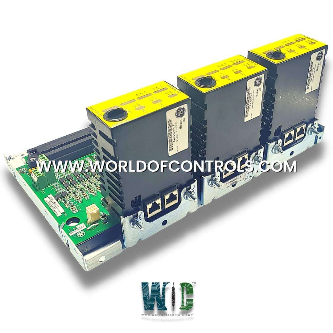
World Of Controls understands the criticality of your requirement and works towards reducing the lead time as much as possible.
IS230TURSH1C - Primary Trip Turbine Protection Board is available in stock which ships the same day.
IS230TURSH1C - Primary Trip Turbine Protection Board comes in UNUSED as well as REBUILT condition.
To avail our best deals for IS230TURSH1C - Primary Trip Turbine Protection Board, contact us and we will get back to you within 24 hours.
SPECIFICATIONS:
Part Number: IS230TURSH1C
Manufacturer: General Electric (GE)
Series: Mark VIe SpeedTronic
Product Type: Primary Trip Turbine Protection Board / Pack
Functional Group: TURS (Turbine Protection & Trip Architecture)
Revision: Group 1, Functional Revision C
Number of Channels: 12 Input/Output Processing Channels
Analog Output Current: 0–20 mA
Common Mode Voltage Range: +5 V DC
Maximum Lead Resistance: 15 Ω
Operating Frequency: 50 Hz / 60 Hz
Operating Temperature: -30°C to +65°C
Dimensions: 8.26 cm H x 4.18 cm W
Weight: 2.0 lbs (0.91 kg)
Conformal Coating: Yes
System Compatibility: GE Mark VIe Control Systems
Availability: In Stock
Repair Lead Time: 3–7 Days
Country of Origin: United States
Manual Reference: GEH-6721
IS230TURSH1C is a Primary Trip Turbine Protection Board designed and manufactured by General Electric as part of the Mark VIe Series used in GE Distributed Turbine Control Systems. This board is responsible for monitoring key operational parameters such as temperature, pressure, and vibration that are critical to the turbine's performance. By continuously assessing these parameters, the protection board can detect any deviations from normal operating conditions. When it identifies that these parameters exceed safe thresholds, it initiates a trip sequence to shut down the turbine, thereby preventing potential damage and ensuring operational safety. The protection board's design often includes redundant systems to enhance reliability and reduce the risk of failure. Furthermore, it provides alarms or notifications for early detection of issues, enabling timely intervention before a full shutdown is necessary. This proactive protection is essential for maintaining the efficiency and longevity of turbine systems, safeguarding both the equipment and overall operational integrity.
INSTALLATION:
Mounting and electrical landing must strictly adhere to industrial cabinet wiring guidelines and system enclosure specifications. Before attempting physical insertion or field wiring removal, isolate all main bus circuit breakers, external excitation power sources, and local logic power supplies, then verify zero voltage potential using calibrated test instrumentation across terminal connections. Secure the hardware module or terminal assembly into the standard cabinet enclosure or rack frame—such as a DIN-rail channel or VMEbus card chassis slot—using specified mounting hardware, ensuring proper ground strap bonding to central panel earth to maintain high noise immunity. Terminate field signal conductors (including current transformer outputs, RTD sensors, or positioning command loops) onto labeled terminal blocks using recommended torque specifications to prevent loose wire faults under continuous industrial vibration, and connect multi-conductor ribbon or shielded multi-pin signal cables (such as DC-37 high-density interfaces or RJ-45 Ethernet IONet links) directly to corresponding header ports with locking tabs or thumbscrews firmly engaged.
OPERATION:
During normal turbine operation and control loop execution, the module functions as a real-time signal interface, protection barrier, or power driver stage within the control system architecture. High-level analog, discrete, or high-speed pickup inputs received from field transducers pass through passive R-C filtering stages and optical or galvanic isolation to prevent systemic ground loops from affecting processing logic. Command setpoints issued by the governor CPU are converted into precise, dither-modulated output currents or relay states to position fuel control valves, steam actuators, and primary trip solenoids. Onboard monitoring logic continuously tracks loop current continuity, channel temperature limits, and backplane telemetry so that if parameter thresholds are violated or wire-break conditions occur, fault flags are immediately transmitted across the backplane for rapid operator alert and trip intervention.
COMPATIBILITY:
The hardware module is designed for seamless integration into specific industrial control system platforms across power generation and heavy turbomachinery applications. In GE SpeedTronic architectures, it is fully compatible with GE Mark VI and Mark VIe Distributed Turbine Control Systems, connecting via standard IONet interfaces and PTBA or TURS terminal board structures. In Woodward governor platforms, the modules are engineered for direct slot installation inside Woodward NetCon, MicroNet, and MicroNet Plus VME control chassis or dedicated load-sharing sensor arrays. Across field device-level interfacing, the hardware supports industry-standard signals including 4–20 mA process loops, 0–5 V DC and 0–10 V DC position feedback, passive magnetic speed pickups, and high-current electro-hydraulic valve coils.
WHY BUY FROM WOC
World of Controls maintains the industry's largest inventory of genuine OEM replacement components exclusively for GE Distributed Mark VIe control systems. To minimize critical plant downtime, we provide both UNUSED surplus and fully REBUILT circuit boards, terminal modules, and I/O packs, each backed by comprehensive warranty protection. Every reconditioned Speedtronic component, including the GE IS230TURSH1C, undergoes thorough diagnostic testing, circuit-level evaluation, and functional bench-testing by our experienced technical team before dispatch. In addition to direct parts supply, our facility offers complete diagnostic repair and unit exchange services with rapid turnaround times for your damaged GE Mark VIe hardware. Our dedicated team of automation specialists is available 24/7 to assist with technical selection, stock verification, and emergency component sourcing for your Speedtronic control panels. Contact us today via phone or email to request pricing, confirm live inventory, or discuss custom repair solutions for your GE Mark VIe infrastructure.
What is GE IS230TURSH1C?
GE IS230TURSH1C is a Primary Trip Turbine Protection Board used in the GE Mark VIe turbine control system. It processes protection-related signals associated with turbine operating conditions. The board supports the control system in identifying abnormal conditions that may require a protective response.
What should I check if a channel is showing an incorrect signal?
Check the field wiring, terminal connections, sensor output, and power supply associated with the affected channel. Measure the signal and lead resistance and compare the readings with the expected values. If the external circuit is operating correctly, the board should be tested for an internal fault.
What can cause an incorrect analog output?
An incorrect analog output can result from faulty sensors, damaged wiring, loose connections, excessive lead resistance, or an unstable power supply. Check the input signal and complete field circuit before replacing the board. If the external signals are correct but the output remains abnormal, further board-level testing may be required.
What should I check if multiple channels show abnormal readings?
First inspect common power supplies, field wiring, terminal connections, grounding, and other shared circuits. Multiple affected channels can indicate a common external issue rather than an individual channel failure. If these checks are satisfactory, inspect the board and associated control-system hardware.
How can I determine whether the board requires repair or replacement?
Verify the power supply, sensors, field wiring, signal levels, lead resistance, and system diagnostics before removing the board. If the external components and signals are within their expected ranges but the fault remains, the board may require diagnostic testing. Repair or replacement can then be considered based on the test results.