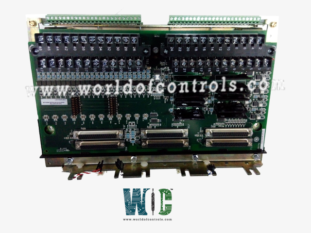
World Of Controls understands the criticality of your requirement and works towards reducing the lead time as much as possible.
IS230TRTDH1D - Resistance Temperature Device Terminal Board is available in stock which ships the same day.
IS230TRTDH1D - Resistance Temperature Device Terminal Board comes in UNUSED as well as REBUILT condition.
To avail our best deals for IS230TRTDH1D - Resistance Temperature Device Terminal Board, contact us and we will get back to you within 24 hours.
SPECIFICATIONS:
Part Number: IS230TRTDH1D
Manufacturer: General Electric
Series: Mark VIe
Number of Channels: 8
Span: 0.3532 to 4.054 V
Maximum lead resistance: 15 Ohm
Operating system: QNX
Product Type: Resistance Temperature Device Terminal Board
Microprocessor: Intel Pentium 133 MHz
Trip Solenoid Rating: 125 V dc
Programming: Boolean
Ethernet interface: Thinwire 10Base2
ISBus interface: Twisted pair RJ-45
Power requirements: +5 V dc
Dimensions: 17.8 cm wide x 33.02 cm
Operating temperature: 0 to 60 °C
No.of Analog Voltage Inputs: 6
Repair: 3-7 Day
Availability: In Stock
Country of Origin: United States
Manual: GEH-6421H
FUNCTIONAL DESCRIPTION:
IS230TRTDH1D is a Resistance Temperature Device Terminal Board manufactured and designed by General Electric as part of the VIe Series used in GE Distributed Control Systems. The TRTD Resistance Temperature Device (RTD) terminal board accepts 16, three- wire RTD inputs. These inputs are wired to two barrier-type terminal blocks. The inputs have noise suppression circuitry to protect against surge and high-frequency noise. TRTD communicates with one or more I/O processors that convert the inputs to digital temperature values and transfer them to the controller. In the Mark VIe system, the PRTD I/O pack works with the TRTD. Only simplex systems are supported. Two PRTD packs plug into the TRTDH1D, and the TRTDH2D, for a total of 16 inputs. There are four versions of TRTD as follows:
INSTALLATION:
The sixteen RTDs are wired directly to two terminal blocks mounted on the terminal board. Each block is held down with two screws and has 24 terminals accepting up to #12 AWG wires. A shield terminal strip attached to the chassis ground is located immediately to the left of each terminal block. In a Mark VI system, TRTDH1B provides redundant RTD inputs by fanning the inputs out to three VRTD boards in the R, S, and T racks. The inputs meet the same environmental, codes, resolution, suppression, and function requirements as with the TRTDH1C terminal board, however, the fast scan is not available.
OPERATION:
The terminal board supplies a 10 mA dc multiplexed (not continuous) excitation current to each RTD, which can be grounded or ungrounded. The 16 RTDs can be located up to 300 m (984 ft) from the turbine control cabinet with a maximum two-way cable resistance of 15 Ω. The A/D converter in the I/O processor board samples each signal and the excitation current four times per second for normal mode scanning, and 25 times per second for fast mode scanning, using a time sample interval related to the power system frequency. Linearization for the selection of 15 RTD types is performed in software. RTD open and short circuits are detected by out-of-range values. An RTD that is determined to be out of hardware limits is removed from the scanned inputs to prevent adverse effects on other input channels. Repaired channels are reinstated automatically in 20 seconds, or can be manually reinstated. All RTD signals have high-frequency decoupling to the ground at signal entry. RTD multiplexing on the I/O processor is coordinated by redundant pacemakers so that the loss of a single cable or loss of a single I/O processor does not cause the loss of any RTD signals in the control database.
WOC has the largest stock of GE Distributed control systems OEM replacement parts. We can also repair your faulty boards and supply unused and rebuilt boards backed up with a warranty. Our team of experts is available round the clock to support your OEM needs. Our team of experts at WOC is happy to assist you with any of your automation requirements. For pricing and availability on any parts and repairs, kindly contact our team by phone or email.
How are RTD terminal boards utilized within turbine control systems?
RTD terminal boards are integrated into the wiring and control systems of turbines to facilitate the connection of RTDs. They provide a centralized point for wiring RTDs, allowing for easier installation, maintenance, and troubleshooting of temperature measurement components.
What specific challenges do RTD terminal boards address in turbine control systems?
RTD terminal boards help overcome challenges related to wiring complexity, ensuring accurate and reliable temperature measurements in various parts of the turbine, such as bearings, shafts, and critical components.
What features should be considered when selecting RTD terminal boards for turbine control systems?
When choosing RTD terminal boards for turbine control systems, factors such as the number of channels (RTD connections), compatibility with RTD types, ruggedness for industrial environments, and safety certifications for hazardous areas should be taken into account.