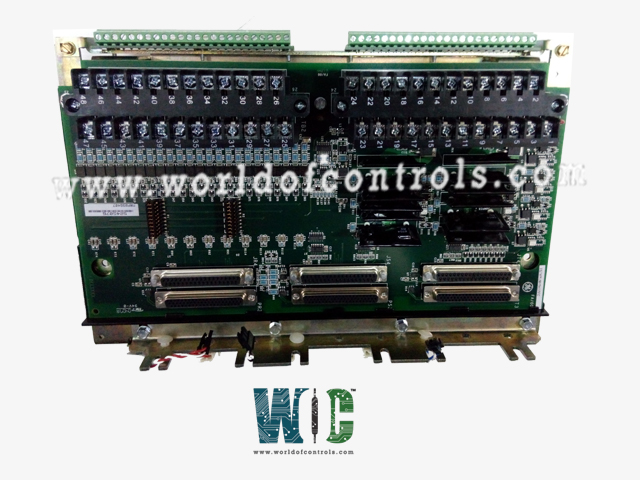
SPECIFICATIONS
Part No.: IS230TRPAH1A
Manufacturer: General Electric
Country of Manufacture: United States of America (USA)
MPU pulse rate range: 2 Hz to 20 kHz
MPU pulse rate accuracy: 0.05% of reading
MPU input circuit sensitivity: 27 mV pk
Size: 33.0 cm high x 17.8 cm , wide
Technology: Surface mount
Temperature: -30 to 65oC
Product Type: Turbine Primary Trip terminal board
Availability: In Stock
Series: Mark VIe
Functional Description
IS230TRPAH1A is a turbine primary trip terminal board developed by GE. It is a part of the Mark VIe control system. The Aeroderivative Turbine Primary Trip TRPA1A and 2A terminal boards are integral components of the Mark VIe / VIeS control system, designed to interface with PTUR / YTUR I/O packs and TTUR terminal boards. These boards play a critical role in monitoring and controlling essential aspects of aeroderivative turbine operation.
Features
- The TRPA1A facilitates precise turbine speed measurement through a combination of passive and active pulse rate devices. Passive pulse rate devices, distributed with four devices per R/S/T section (a total of twelve), detect toothed wheel rotations to provide accurate speed data. Alternatively, six active pulse rate inputs, offering redundancy with two inputs per TMR section, ensure reliable speed monitoring.
- The boards include four voltage detection circuits designed to monitor the trip string within the 24-125 V DC range. Continuous monitoring of critical voltages ensures safe operating conditions and early detection of potential issues, enhancing system reliability.
- An integral safety feature is the fail-safe ESTOP input operating within the 24-125 V DC range. This input is crucial for emergencies, allowing for immediate removal of power from trip relays to prevent unintended turbine operation or trip initiation.
- Integration within the TMR system architecture involves connecting to various connectors such as PR3, PS3, PT3, JR4, JS4, and JT4. This ensures robust communication and operational continuity, essential for maintaining turbine performance and safety standards.
Wiring and Terminal Blocks
- TB1: This terminal block accommodates TTL pulse rate pickups, voltage detection circuits, Emergency Stop (E-Stop) inputs, and connections to the breaker relay. It is securely fastened with two screws and features 24 terminals capable of accepting wires up to #12 AWG (American Wire Gauge). Adjacent to TB1, a shield termination strip connected to chassis ground provides essential grounding for reliable signal integrity.
- TB2: Dedicated to passive pulse rate pickups, TB2 streamlines the wiring process by organizing connections specifically for these sensors. Like TB1, it is also secured with two screws and offers 24 terminals suitable for 12 AWG wires.
Configuration Requirements
- Speed Input Configuration: The system requires configuration to specify the connections for speed inputs. This configuration is facilitated using a designated table that outlines the necessary settings.
- Jumpers JP1 and JP2: These jumpers play a critical role in configuring the system. They are used to select how the pulse rate pickups from the R section are distributed (fanned out) to the S and T PTURs or YTURs. This selection ensures that the speed inputs are correctly routed and synchronized within the control system architecture.
Installation Procedure
- Prepare and Secure Terminal Blocks: Begin by mounting TB1 and TB2 securely using the provided screws. Ensure that both terminal blocks are firmly attached to the designated mounting points, facilitating stable and reliable connections.
- Connect TTL Pulse Rate Pickups, Voltage Detection, E-Stop, and Breaker Relay: Utilize TB1 to connect TTL pulse rate pickups, voltage detection circuits, E-Stop inputs, and the breaker relay. Carefully route and connect each wire according to the designated terminals, ensuring proper alignment and secure attachment to maintain signal integrity and operational safety.
- Wire Passive Pulse Rate Pickups to TB2: TB2 is specifically designated for passive pulse rate pickups. Organize and connect the wires from these sensors to the appropriate terminals on TB2. Secure each connection to prevent accidental disconnection and ensure reliable operation during turbine monitoring and control.
- Configure Jumper Settings (JP1 and JP2): Refer to the configuration table to determine the appropriate settings for jumpers JP1 and JP2. Adjust these jumpers as specified to ensure correct fanning of pulse rate pickups from the R section to the S and T PTURs or YTURs. This configuration step is crucial for synchronizing speed inputs effectively within the TRPA system.
The WOC team can always help you with your Mark VIe requirements. For more information, please contact WOC.
Frequently Asked Questions
What is IS230TRPAH1A?
It is a turbine primary trip terminal board developed by GE under the Mark VIe series.
What is the purpose of monitoring feedback from the shorted contact detector?
The feedback from the shorted contact detector is crucial for detecting any issues with control signals. If a problem is detected, such as a short circuit or malfunction, an alarm is triggered. This proactive monitoring ensures prompt identification of control signal failures, allowing for timely corrective action to maintain system integrity and operational safety.
Why is feedback from the ESTOP/TRP input monitored?
Monitoring feedback from the Emergency Stop (ESTOP) or Trip (TRP) input is essential to ensure the reliability of safety signals. If there is any problem with the ESTOP/TRP signal, such as a fault or loss of signal, a fault condition is generated. This ensures that any potential safety hazards are promptly addressed, preventing unintended operations or hazards to personnel and equipment.
What is the role of monitoring speed pickup fanning jumpers?
The speed-pickup fanning jumpers facilitate the correct distribution of speed pickup signals within the control system. Monitoring this feedback ensures that the actual configuration matches the intended setup. If there is a mismatch between the intended and actual positions of these jumpers, indicating a configuration error, an alarm is generated. This helps maintain accurate speed monitoring and synchronization within the system, which is critical for operational efficiency and turbine performance.
