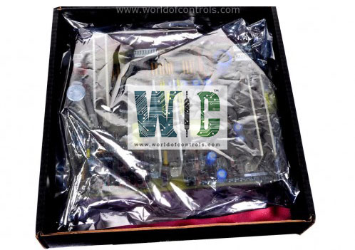
World Of Controls understands the criticality of your requirement and works towards reducing the lead time as much as possible.
IS230TRLYH2F - Relay Output Terminal Board is available in stock which ships the same day.
IS230TRLYH2F - Relay Output Terminal Board comes in UNUSED as well as REBUILT condition.
To avail our best deals for IS230TRLYH2F - Relay Output Terminal Board, contact us and we will get back to you within 24 hours.
SPECIFICATIONS:
Part Number: IS230TRLYH2F
Manufacturer: General Electric (GE)
Series: Mark VIe
Board Type: Relay Output Terminal Board (Compact)
Relay Count: 12 Magnetic Relays
Board Types: H1F, S1F
Rated Voltage on Relays: Nominal 115 V ac
Relay Type: Form-C (Dry Contact)
Max Contact Voltage: 125 VDC / 250 VAC
Max Response Time On: 25 ms
Max Contact Current: 5A Continuous
I/O Pack Compatibility: IS220PRLYH1B / IS220PRLYH1A
Connectors: 2x 37-pin D-type (JR1, JS1)
Mounting: DIN-rail or Sheet Metal
Operating Temp: -30 °C to +65 °C (-22 °F to +149 °F)
Size: WPDF 10.16 cm wide x 33.02 cm high
FUNCTIONAL DESCRIPTION:
IS230TRLYH2F is a Relay Output Terminal Board manufactured and designed by General Electric as part of the Mark VI Series used in GE Distributed Turbine Control Systems. The Relay Output with TMR contact voting (TRLY_1F and TRLY_2F) terminal boards provide 12 contact-voted relay outputs. The board holds 12 sealed relays in each TMR section, for a total of 36 relays. The relay contacts from R, S, and T are combined to form a voted Form A (NO) contact with TRLY_1F, or the voted contacts are Form B (NC) output with TRLY_2F. Either 24/125 V dc or 115 V ac can be applied. TRLY_F boards do not support simplex applications and lack power distribution.
An optional power distribution board, IS200WPDFH1A, can be added so that a standard 125 V dc or 115 V ac source, or an optional 24 V dc source with individual fuses, can be provided for field solenoid power. IS200WPDFH2A provides a single fuse in the high side (pin 1 of J1–J4) of each power distribution circuit for AC applications where a fuse in neutral return wire (pin 3 of J1–J4) is not desirable.
To reduce confusion in troubleshooting this highly interactive board set and to reduce mean time-to-repair, for first-stage troubleshooting, the TRLY_#F/WPDF should be treated as the lowest replaceable unit (LRU) and replaced as a set when the diagnostic messages indicate that either is involved. If necessary, when time and conditions permit, the individual failed board can be further isolated using golden boards (a board previously known to be good) to match with the individual suspect board.
TRLYH2F INSTALLATION:
Connect the wires for the 12 solenoids directly to two I/O terminal blocks on the terminal board. Each block is held down with two screws and has 24 terminals accepting up to #12 AWG wires. A shield termination strip attached to chassis ground is located immediately to the left side of each terminal block. Solenoid power for outputs 1-12 is available if the WPDF daughterboard is used. Alternatively, customer power may be wired to the terminal block. The 28 V dc power for the terminal board relay coils and logic comes from the three I/O packs connected at JR1, JS1, and JT1.
WPDF POWER DISTRIBUTION BOARD:
If using the optional WPDF power distribution board, mount it on top of the TRLY on the J1 and J2 connectors. Secure the WPDF to the TRLY by fastening a screw in the hole located at the center of the WPDF. Connect the power for the two sections of the board on the three-pin connectors J1 and J4. Power can be daisy-chained out through the adjacent plugs, J2 and J3.
TRLYH2F OPERATION:
The 28 V dc power for the terminal board relay coils and logic comes from the three I/O packs connected at JR1, JS1, and JT1. The same relays are used for ac voltages and dc voltages. The TRLY_#F terminal board uses the same relays with differing circuits. Relay drivers are mounted on the TRLY_#F and drive the relays at the frame rate. The relay outputs have a fail-safe feature that votes to de-energize the corresponding relay when a cable is unplugged or communication with the associated I/O pack is lost. This board only supports TMR applications. The relay control signals are routed into TRLY_#F from the three I/O packs R, S, and T through plugs JR1, JS1, and JT1. These signals directly control the corresponding relay driver for each TMR section R, S, and T. Power for each section’s relay coils comes in from its own I/O pack and is not shared with the other sections. TRLY_#F features TMR contact voting. The relay contacts from R, S, and T are combined to form a voted Form A (NO) contact with TRLY_1F or a Form B (NC) output with TRLY_2F. 24/125 V dc or 115 V ac can be applied. The following figure displays the TMR voting contact circuit.
WHY BUY FROM WOC:
World of Controls supports the critical safety and control needs of your GE Mark VIe systems by offering the PDIIH1A in both UNUSED and REBUILT conditions. Every PDII pack is rigorously tested on specialized diagnostic benches to verify isolation integrity, channel response times, and network redundancy. We maintain a comprehensive inventory of isolated discrete I/O to ensure your power plant and industrial operations stay protected. With global logistics and 24/7 technical expertise, WOC is your trusted source for high-reliability Speedtronic hardware.
What is the GE IS230TRLYH2F?
It is a 12-point Relay Output Terminal Board used in the Mark VIe system. It translates digital commands from the controller into physical contact closures to drive field devices like valves and motors.
What is the primary difference between the TRLYH1B and the TRLYH2F?
The TRLYH1B is the larger standard version with 24 relays, whereas the IS230TRLYH2F is a compact version featuring 12 relays. The H2F is typically utilized in applications where cabinet space is limited or where fewer output points are required per processor.
How do I troubleshoot a Relay Feedback Mismatch alarm?
This indicates the sensed state of the relay does not match the commanded state. Check the 28V DC power to the I/O pack, verify the continuity of the Form-C contacts with a multimeter, and inspect the 37-pin cable for bent pins or poor seating.
What is the maximum current rating for the contacts?
Each of the 12 relays is rated for 5A continuous current at 125 VDC or 250 VAC. For loads exceeding this or those with high inrush currents, external interposing relays should be utilized.
What are the voltage and current limits for the H2F relays?
Each of the 12 magnetic relays is rated for 5A continuous current at a maximum of 125 VDC or 250 VAC. For loads exceeding these parameters, an external interposing relay should be installed.