World Of Controls understands the criticality of your requirement and works towards reducing the lead time as much as possible.
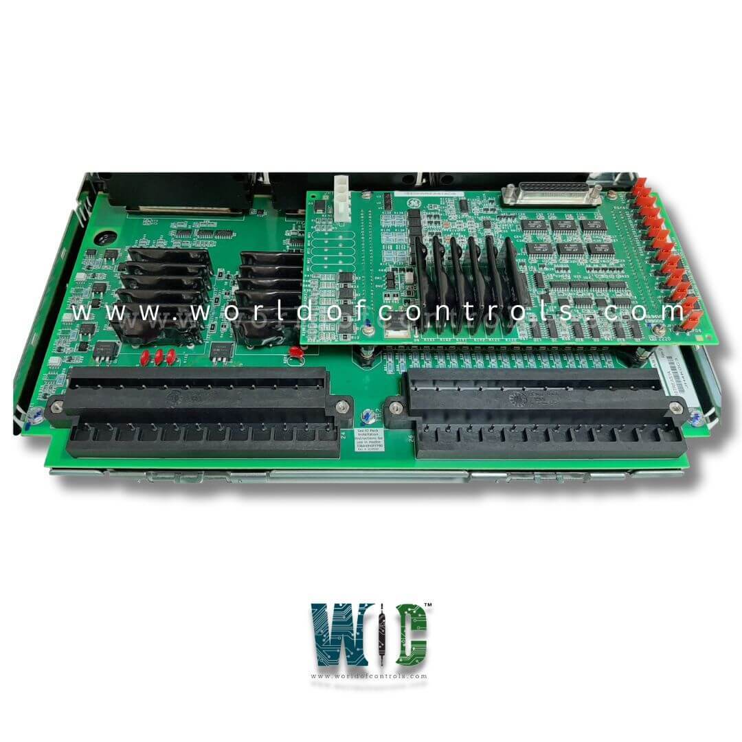
IS230TREAH5A - Turbine Emergency Trip Terminal Board is available in stock which ships the same day.
IS230TREAH5A - Turbine Emergency Trip Terminal Board comes in UNUSED as well as REBUILT condition.
To avail our best deals for IS230TREAH5A - Turbine Emergency Trip Terminal Board, contact us and we will get back to you within 24 hours.
SPECIFICATIONS:
Part Number: IS230TREAH5A
Manufacturer: General Electric
Series: Mark VIe
Number of Channels: 8
Maximum lead resistance: 15 Ohms
Operating system: QNX
Product Type: Turbine Emergency Trip Terminal Board
Microprocessor: Intel Pentium 133 MHz
Trip Solenoid Rating: 125 V dc
Programming: Boolean
Ethernet interface: Thinwire 10Base2
ISBus interface: Twisted pair RJ-45
Power requirements: +5 V dc
Dimensions: 17.8 cm wide x 33.02 cm
Operating temperature: 0 to 60°C
No.of Analog Voltage Inputs: 6
Repair: 3-7 Days
Availability: In Stock
Country of Origin: United States
Manual: GEH-6421D
FUNCTIONAL DESCRIPTION:
IS230TREAH5A is a Turbine Emergency Trip Terminal Board manufactured and designed by General Electric as part of the VIe Series used in GE Distributed Control Systems. The turbine emergency trip terminal board, TREAH1A, works with PPRO turbine I/O packs as part of the Mark VIe system. The inputs and outputs are as follows:
INSTALLATION:
For H1 and H2 board variants, voltage detection and the breaker relay are wired to the I/O terminal blocks TB1. Passive pulse rate pick-ups are wired to TB2. Each block is held down with two screws and has 24 terminals accepting up to #12 AWG wires. A shield termination strip attached to the chassis ground is located immediately to the left of each terminal block. For H3 and H4 board variants, voltage detection and the breaker relay are wired to the I/O box terminals at the top of the board. Passive pulse rate pick-ups are wired to the lower terminals. All terminals plug into a header on the TREA board and accept up to a single #12 AWG wire.
E-STOP/TRP INPUT:
As the TRP is very fast < 5 ms and the output relay contacts are also fast (< 15 ms), best wiring practices should be utilized to avoid disoperation. Use twisted-pair cable when possible and avoid running with ac wiring.
OPERATION:
When used with PPRO I/O packs mounted directly on the TREA, the speed inputs provide two options. Each PPRO I/O pack may receive a dedicated set of three-speed inputs from its respective TREA terminal points, as is done on SPRO. As an option, jumpers P1 and P2 may be placed on the TREA to take the first three speed inputs (those for the X pack) and fan them to the Y and Z packs. When this is selected, the terminal board points for Y and Z. Speed inputs become no-connect and should not be used. As a check, the PPRO is configured for fanned or direct speed input and a feedback signal provided by TREA. An alarm will be generated if there is a mismatch between the jumper position and the PPRO configuration.
The TREA includes an EStop function. This consists of an optically isolated input circuit designed for a DC input in the range of 24 V to 125 V nominal. When energized, the circuit enables coil drive power in the X, Y, and Z relay circuits through independent hardware paths. The response time of this circuit of less than five milliseconds, plus the response time of the trip relays of less than one millisecond, yields a very fast EStop response. EStop is monitored by PPRO firmware, but the action to remove the trip relay coil power is a hardware path in PPRO. It is possible to configure PPRO to turn off the Estop function.
WORLD OF CONTROLS is your trusted source for GE Distributed Control System (DCS) replacement parts, offering the largest inventory of genuine OEM components, including new, refurbished, and tested parts, all backed by warranty. We also provide expert repair services for faulty boards, ensuring top-quality performance and reliability. Our dedicated team is available 24/7 to support your automation needs with fast turnaround, competitive pricing, and comprehensive technical assistance. For pricing and availability, contact us today and keep your systems running efficiently with WOC’s trusted solutions.
How can I troubleshoot a non-responsive board?
Start by verifying the power supply, then check input signal continuity and fuse status. Inspect the PCB for burnt components, cracked solder joints, or corrosion on connectors. Use diagnostic LEDs if available to identify fault locations.
What should I do if the board trips without any input signals?
Check for power supply fluctuations, loose connections, or short circuits on the input lines. Inspect relays and PCB for signs of damage or leakage. False trips are often caused by grounding issues or signal interference.
How do I verify the DC power supply to the trip board?
Measure the DC voltage at the board input terminals using a multimeter. Ensure the voltage is within the specified range, typically 24 VDC ± 10%. Check for loose connections, blown fuses, or voltage drops under load.