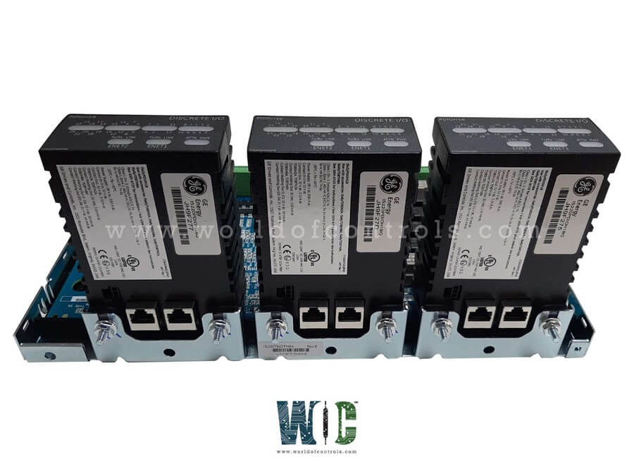
World Of Controls understands the criticality of your requirement and works towards reducing the lead time as much as possible.
IS230TNIDH4A - Discrete Input DIN-Rail Module is available in stock which ships the same day.
IS230TNIDH4A - Discrete Input DIN-Rail Module comes in UNUSED as well as REBUILT condition.
To avail our best deals for IS230TNIDH4A - Discrete Input DIN-Rail Module, contact us and we will get back to you within 24 hours.
SPECIFICATIONS:
Part Number: IS230TNIDH4A
Manufacturer: General Electric
Series: Mark VIe
Product Type: Discrete Input DIN-Rail Module
Input Channels: 24
Input Voltage Range: 0 � 30 VDC
Input ON Threshold: 15 VDC
Isolation Voltage: 1500 V RMS
Input Current (per channel): 2.5 � 7 mA
Mounting: Standard 35 mm DIN Rail
Operating temperature: -40 to +70�C
Size: 15.9 cm high x 17.8 cm
Weight: 0.8kg
Repair: 3-7 days
Availability: In Stock
Country of Origin: United States
FUNCTIONAL DESCRIPTION:
IS230TNIDH4A is a Discrete Input DIN-Rail Module manufactured and designed by General Electric as part of the Mark VIe Series used in GE Distributed Turbine Control Systems. A Discrete Input DIN-Rail Module is designed to detect and process binary (ON/OFF) field signals originating from mechanical switches, dry contacts, proximity sensors, and protection relays. These modules serve as a critical link between field instrumentation and the control system by translating high-voltage or contact-based input signals into isolated logic-level signals suitable for digital processing. Typically, each module contains 8 to 32 optically isolated input channels, each capable of detecting a voltage threshold (commonly 24 VDC, but may range from 5 VDC to 125 VDC depending on the model). Each channel incorporates input conditioning circuitry, overvoltage protection, current limiting, and noise filtering. The isolation barrier (often 1500 V RMS) between the field side and logic side ensures protection against transient voltage, ground loops, and external electrical disturbances. Some modules support diagnostic features such as input loss detection, line monitoring, and event timestamping when used in turbine or safety-critical applications.
OPERATION:
The module continuously monitors voltage presence at each input terminal. When a voltage within the specified threshold is applied (typically 15�30 VDC for a 24 V system), the internal opto-isolator or transformer-based circuitry detects the voltage and converts it into a logic 1 at the module�s internal register. If the voltage falls below the lower threshold (typically 5 VDC), the input state is interpreted as logic 0. The logic states are sampled by an on-board microcontroller or I/O processor, which buffers and communicates the channel statuses to the control system (via Ethernet, serial link, or backplane bus, depending on the architecture). In GE Mark VIe systems, this may occur via PDIA packs, which interface the TICI module to the controller. The module often supports configurable debounce time or filtering (e.g., 1 ms to 20 ms) to eliminate false triggering caused by signal noise or mechanical bounce. In redundant systems, input voting and synchronization may be performed across multiple modules to ensure fault tolerance.
INSTALLATION:
The module is mounted on a standard EN 60715 35 mm DIN rail, ensuring compatibility with standard industrial enclosures. Adequate spacing must be maintained for ventilation, and grounding lugs or shield terminals should be connected to the panel�s chassis ground for EMC compliance. Wiring to the input terminals is performed using twisted-pair or shielded cables, typically rated for 300�600 V and sized between 18�12 AWG, depending on the terminal rating. Terminal blocks are often pluggable or screw-type, with clear labeling for channel numbers, return paths, and shield connections. Each input device (e.g., limit switch or relay output) is wired to a dedicated input channel, with the common or return tied to the module�s input ground (often isolated from logic ground). Modules may be powered via a dedicated 24 VDC power supply or derive power from a backplane. After wiring, the system software (e.g., ToolboxST for GE Mark VIe) is used to configure each channel�s behavior, such as active-high/low logic, debounce settings, line monitoring, or fault detection thresholds.
WOC maintains the largest inventory of replacement parts for GE Distributed Control Systems. We supply both unused and rebuilt components, each covered by a warranty. In addition, we offer expert repair services for malfunctioning boards. Our team of automation specialists is available 24/7 to support your OEM needs. For parts, repairs, or technical assistance, please contact us via phone or email. We are committed to providing prompt and reliable support.
What is the input voltage range for the module?
The typical input voltage range is 0�30 VDC, with a nominal value of 24 VDC. Input is considered ON at 15 VDC and OFF at 5 VDC. Some modules support extended ranges like 48 VDC or 125 VDC.
What is the debounce time for digital inputs?
Debounce filtering removes noise and contact bounce from mechanical switches. This filtering is usually software-configurable between 1 ms and 20 ms. It ensures stable and reliable signal recognition.
How is the module connected to the controller?
It connects via a backplane or I/O pack such as GE PDIA, using serial or Ethernet protocols. The controller reads buffered input states at a fixed scan rate. Input state changes are processed in software with event capture, if supported.