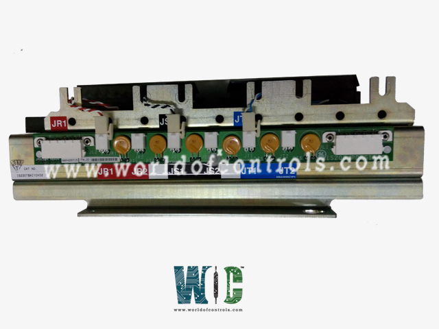
SPECIFICATIONS
Part No.: IS230TBAI1CH02
Manufacturer: General Electric
Temperature -30 to 65 oC (-22 to +149 oF)
Size 10.16 cm wide x 33.02 cm high ( 4.0 in x 13 in)
Product Type: Analog Input terminal board
Availability: In Stock
Country of Manufacture: United States (USA)
Functional Description
IS230TBAI1CH02 is an analog input terminal board developed by GE. It is a part of Mark VIe control system. The Analog Input terminal board (TBAI) is a versatile component designed to facilitate analog input and output functionalities within the system. Its compatibility with both simplex and TMR configurations further enhances system resilience and redundancy, ensuring continuous operation and performance optimization.
Analog Inputs
- Quantity: TBAI supports up to 10 analog inputs, accommodating various transmitter types including two-wire, three-wire, four-wire, or externally powered transmitters.
- Flexibility: These inputs offer flexibility in accommodating different transmitter configurations, ensuring compatibility with diverse sensor setups.
Analog Outputs
- Quantity: TBAI features two analog outputs, configurable for either 0-20 mA or 0-200 mA current output ranges.
- Customizable: Users have the flexibility to configure the output range according to specific system requirements, enhancing adaptability and versatility.
Noise Suppression Circuitry
- Protection: Both inputs and outputs are equipped with noise suppression circuitry, safeguarding against surge and high-frequency noise. This feature ensures reliable and accurate signal transmission, even in challenging operating environments.
Connectivity Options
- Connectors: TBAI provides three DC-37 pin connectors for connection to the I/O processors, offering flexibility in system configuration.
- Simplex or TMR Configuration: Connections can be simplex, utilizing a single connector (JR1), or Triple Modular Redundant (TMR), utilizing all three connectors.
- Cabling Options: Connections may be established through cables or directly to the electronics, providing flexibility in installation and setup.
TMR Operation
- Signal Distribution: In TMR applications, input signals are distributed to the three connectors corresponding to the R, S, and T controls, ensuring redundancy and fault tolerance.
- Output Operation: TMR outputs function by combining the current of the three connected output drivers, with the total current measured using a shunt on the TBAI.
- Regulation: The TBAI regulates the total current signal presented to the electronics, ensuring precise control and regulation to the commanded setpoint.
Configuration
- Jumpers J1A through J8A: These jumpers determine whether the input is configured for current input or voltage input. The specific configuration is selected based on the desired input type.
- Jumpers J1B through J8B: These jumpers dictate whether the return is connected to common or left open, providing flexibility in grounding configurations.
- Jumpers J9A and J10A: These jumpers offer a choice between 1 mA or 20 mA input current, allowing users to customize the input current according to specific requirements.
- Jumpers J9B and J10B: Similar to J1B through J8B, these jumpers determine whether the return is connected to common or left open, providing additional flexibility in grounding configurations for specific input currents.
- Jumper J0: Jumper J0 is responsible for setting output 1 to either 20 mA or 200 mA, enabling users to configure the output current based on their application needs.
- Additional Configuration: Beyond jumper settings, all other configurations, particularly those related to VAIC (Voltage Analog Input Card) or PAIC (Programmable Analog Input Card), are performed using specialized tools available in the toolbox. These tools provide comprehensive options for fine-tuning and customizing the terminal board's operation to suit specific application requirements.
Features
- Number of Channels: Each terminal board supports 12 channels, comprising 10 Analog Inputs (AI) and 2 Analog Outputs (AO), offering extensive connectivity options.
- Input Span for Transmitters: Transmitters are compatible with input spans ranging from 1-5 V DC, translating to a 4-20 mA current input, ensuring versatility in signal processing and interpretation.
- Outputs: The terminal board delivers 24 V outputs with a current capacity of 21 mA per connection, ensuring sufficient power for connected devices.
- Maximum Lead Resistance: A maximum lead resistance of 15 ohms ensures reliable signal transmission over distances of up to 300 meters (984 feet), catering to installations across large industrial environments.
- Fault Detection: The terminal board features built-in fault detection mechanisms to monitor total output current, enhancing system reliability and performance.
- Hardware Compatibility: Hardware compatibility is ensured through the monitoring of connector ID chips, mitigating the risk of compatibility issues and ensuring seamless integration within the system architecture.
World of Controls has the most comprehensive collection of GE Mark VIe components. Please contact WOC as soon as possible if you require any extra information.
Frequently Asked Questions
What is IS230TBAI1CH02?
It is an Analog Input terminal board developed by GE
How does the board indicate the output current?
The board utilizes a series resistor to measure the voltage drop across it, providing an indication of the output current. This method allows for accurate monitoring of current flow through the outputs.
How are cable connectors on the terminal board identified?
Each cable connector on the terminal board is equipped with its own identification (ID) device. This read-only chip contains crucial information such as the terminal board serial number, board type, revision number, and the connector location (JR, JS, JT).
What action is taken if a mismatch is detected in the ID device?
When the I/O controller interrogates the ID device on a cable connector and detects a mismatch in the encoded information, it triggers a hardware incompatibility fault. This fault serves as an alert to potential discrepancies in the configuration or connection of the terminal board, prompting corrective action to ensure compatibility and system integrity.
