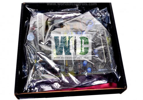
World Of Controls understands the criticality of your requirement and works towards reducing the lead time as much as possible.
IS230STURH3A - Simplex Primary Turbine Protection Input Terminal Board is available in stock which ships the same day.
IS230STURH3A - Simplex Primary Turbine Protection Input Terminal Board comes in UNUSED as well as REBUILT condition.
To avail our best deals for IS230STURH3A - Simplex Primary Turbine Protection Input Terminal Board, contact us and we will get back to you within 24 hours.
TECHNICAL SPECIFICATIONS:
Part Number: IS230STURH3A
Manufacturer: General Electric (GE) / GE Vernova
Series: Mark VIe & Mark VIeS
Functional Acronym: STUR
Product Type: Primary Turbine Protection Input Terminal Board
Hardware Revision: REV A
Redundancy Configuration: Simplex (S-Type)
I/O Pack Interface: One DC-62 pin connector matching the PTUR pack
Trip Board Linkage: One DC-37 pin connector matching the trip relay boards
Terminal Blocks: Two rows of 24-point pluggable strips
Overspeed Inputs: 4 channels for passive MPU or active sensors
Sensing Voltage Ranges: Dual PT inputs (16 V DC to 140 V DC tracking)
Trip Solenoid Outputs: Two channels monitored by K1 and K2 safety relays
Circuit Board Protection: High-grade Conformal PCB Coating
Ambient Operating Temperature: -30°C to +65°C (-22°F to +149°F)
Repair Lead Time: 3–5 Business Days
Availability: In Stock / Repair & Exchange Available
Country of Origin: United States
The IS230STURH3A is a Simplex Primary Turbine Protection Input Terminal Board designed and manufactured by General Electric for the Speedtronic Mark VIe control ecosystem. The GE IS230STURH3A (STUR) is a simplex S-type terminal board used as a simplified version of the turbine terminal board (TTUR). It provides connections for turbine-specific primary trip (PTUR) functions, speed inputs, synchronizing inputs, and trip relay outputs, or supports a cable interface to drive a primary trip board.
The STUR is typically used in applications such as mechanical drive systems that require overspeed protection without synchronization, generator drive systems that need both overspeed protection and primary synchronization, and other setups that utilize the four pulse input circuits associated with PTUR. It maintains the same physical dimensions, customer terminal layout, and I/O pack mounting arrangement as other S-type terminal boards. Additionally, its design ensures that no components extend above the attached PTUR I/O pack, allowing for double stacking of terminal boards where required.
TURBINE FREQUENCY SCANNING & INTERFACING:
The card architecture is structurally optimized to capture, isolate, and route raw operational speed waveforms without introducing data bus delays or processing latency. The termination block supports up to four speed pulse input loops connected directly to active proximity probes or passive magnetic pickups (MPUs) facing a toothed wheel on the main turbine rotor shaft.
The onboard hardware layer cleans incoming frequency variations through high-impedance filtering circuits to process raw alternating current inputs. This optimizes zero-crossing detection parameters across variable physical gear tooth dimensions while maintaining baseline signal validation to differentiate zero rotor RPM from open-loop line breaks. It then channels these precise pulse streams across the DC-62 pin connector interface directly to the underlying PTUR Primary Turbine Protection input/output pack for real-time overspeed processing and calculation.
POWER ACQUISITION & SYNCHRONIZATION MATRIX:
The Turbine Protection Input Terminal Board accommodates automated generator-to-grid synchronization sequences. It tracks phase, frequency, and wave amplitude parameters by executing real-time measurements across two separate Potential Transformer (PT) analog input lines.
These hardware traces monitor the live electrical bus voltage and the turbine generator output terminals. The analog bus and generator potential transformer circuits utilize galvanic isolation transformers coupled with physical hardware filtering to sample AC waveforms safely without exposing the underlying 62-pin logic interface to common-mode electrical transients or grounding grid offsets. This allows the Mark VIe synchronization algorithm to safely command main breaker closures via on-board secondary control paths.
OPERATION:
STUR is available in four distinct configurations. STUR is not available with fixed box terminals. It uses pluggable type terminals. Two groups offer on-board trip relays, and two groups offer DC-37 pin connectors for using an external trip board. Components supporting generator applications will be omitted from the two groups used for mechanical applications and added to the groups used for generator applications. STUR provides four speed input circuits that accept passive speed sensors or active speed sensors. When passive sensors are used, the signal is applied between terminals PR#_H and PR#_L, where # is 1 through 4. Sensitivity of the passive sensor input is such that the PTUR I/O pack is able to sense speeds as low as 2RPM. When active speed sensors are used, the signal is applied between terminals TTL# and PR#_L.
PRIMARY SYNCHRONIZING:
STURH2 and STURH4 used with PTUR provide support for synchronized closure of a 52G primary breaker. Two PT inputs are provided for Bus and Generator voltage on terminals 21 through 24. Breaker positive power at 24, 48, or 125 V dc is applied to terminal 27 (PGEN), and the return is applied to terminal 32 (NGEN). The presence of this voltage is indicated by the BKRVLT signal. Positive power passes through a permissive relay K25P to terminal 28 (AUTO) with power indicated by the BKRPRM signal. Power then passes through the synchronizing pilot relay K25 to terminal 29 (MAN) as indicated by the BKRGES signal. If a backup sync-check relay is used, it is to be wired between terminals 29 and 30 (BKRH) with closure indicated by signal BKRGXS. If a backup sync-check is not used, a jumper between terminals 29 and 30 is used to complete the circuit, and BKRGXS and BKRGES both indicate that power is applied to the breaker coil. The breaker coil or a pilot relay is to be wired between terminals 31(BKRH) and 32 (NGEN).
WHY PARTNER WITH WORLD OF CONTROLS:
World of Controls provides the industry's most dependable logistics and technical infrastructure for critical turbine control networks. We maintain an extensive inventory of genuine OEM replacement parts for GE Distributed control setups, minimizing operational downtime during emergency outages. Every item, from certified unused surplus to fully rebuilt industrial components, is subjected to strict simulation profiling in our advanced electronics lab and is supplied with a comprehensive product warranty. Our global engineering support network operates 24/7 to deliver troubleshooting advice, component replacement guidance, and component testing evaluations. Contact the WOC sales team directly via phone or email for current pricing, hardware availability, or repair quotes.
What is the GE IS230STURH3A?
The GE IS230STURH3A is a Simplex Primary Turbine Protection Input Terminal Board designed for the Mark VIe control system. It acts as a dedicated field termination module that gathers and routes overspeed data, synchronization signals, and emergency trip commands to a central processing unit.
What is the exact terminal point capacity of the IS230STURH3A terminal boards?
The board features a total termination capacity of 48 connection points. These points are structurally organized into two rows of 24-point pluggable Euro-style box connector strips. This modular setup allows field technicians to disconnect entire wiring blocks quickly during maintenance without altering individual field wires.
How many independent overspeed pickup channels are built into the board hardware?
There are 4 dedicated channels integrated into the circuit board architecture to capture rotational dynamics. These channels interface seamlessly with either active proximity probes or passive magnetic pickup (MPU) sensors tracking the rotor shaft. The multi-channel framework ensures comprehensive frequency capturing for precise overspeed validation.
What is the continuous voltage input range for the potential transformer synchronization circuits?
The potential transformer tracking circuits accommodate a continuous voltage monitoring range spanning from 16 V DC up to 140 V DC. This wide tracking index allows the system to accurately evaluate and sample alternating current waveforms. This real-time scaling is critical for managing generator-to-grid auto-synchronization sequences.
How many pins are configured on the primary and auxiliary cable connection headers?
The board incorporates a main 62-pin right-angle connector alongside an auxiliary 37-pin connector interface. The high-density 62-pin header bridges raw field signals directly to a mated companion PTUR processing pack. Meanwhile, the 37-pin trace establishes a dedicated link to heavy-duty mechanical emergency trip relay boards.
What electrical isolation threshold protects the logic interface from the synchronization lines?
A robust 1500 V RMS galvanic isolation boundary is built into the potential transformer lines to insulate the core microprocessor elements. This isolation is achieved using high-grade, surface-mounted toroidal isolation transformers combined with hardware filtering networks. The layout completely blocks common-mode electrical transients, line spikes, or grounding differentials from corrupting the logic rails.
How many physical safety relays are mounted to drive the emergency trip string loops?
The board features 2 onboard physical safety relays, specifically designated as K1 and K2, to supervise the active trip solenoids. These components act as a hardwired fail-safe network that drops power to the primary turbine trip loops the instant an emergency condition is declared. This series relay architecture guarantees rapid, hardware-enforced emergency shutoffs independent of core software status.