SPECIFICATIONS
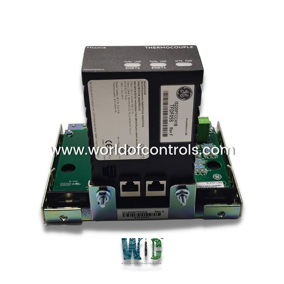
Part Number: IS230SNTRH3A
Manufacturer: General Electric
Series: Mark VIe
Function: Primary Turbine Protection Module
Availability: In Stock
A/D converter resolution: 14-bit resolution
Country of Manufacture: United States (USA)
Functional Description
IS230SNTRH3A is a Primary Turbine Protection Module manufactured and designed by General Electric. It is a part of the Mark VIe Control System. Turbine overspeed protection encompasses three levels of safeguarding; control, primary, and emergency. Each level serves a distinct purpose in ensuring the safe operation of the turbine under varying conditions. Control protection is implemented through closed-loop speed control mechanisms utilizing the fuel/steam valves. Primary overspeed protection is inherent to the controller itself. The terminal board and I/O pack interface with the turbine's shaft speed signal, transmitting this data to each controller within the system. In cases of critical overspeed conditions beyond the control or primary protection levels, emergency overspeed protection mechanisms are activated. The trip signal received by the terminal board is processed through a three-relay voting circuit, ensuring redundancy and reliability.
Backup Synch Check Protection
- Voltage Supply and Cable Requirements: The generator and bus voltages are sourced from two single-phase potential transformers (PTs) with secondary outputs providing a nominal 115 V rms. To ensure reliable transmission of voltage signals, the maximum allowable cable length between the PTs and the turbine control is limited to 100 meters. Twisted, shielded wire with a gauge of 18 AWG is recommended for optimal performance.
- PT Characteristics: Each PT is equipped with magnetic isolation and features a 1,500 V rms rated barrier to prevent voltage surges and ensure electrical safety.
The circuit load of each PT is kept below 3 VA, minimizing power consumption and optimizing efficiency during operation.
- Synch Algorithm and Accuracy: The synch algorithms employed in the backup synch check protection system utilize phase lock loop (PLL) techniques to synchronize the generator and bus voltages effectively. The phase error between the generator and bus voltages is maintained at less than +/-1 degree at nominal voltage and 50/60 Hz, ensuring precise synchronization and alignment. The system supports a frequency range of 45 to 66 Hz, with the measured frequency remaining within 0.05% of the input frequency. This level of accuracy ensures reliable synchronization across varying frequency conditions.
- Illustrative Algorithm: The synchronization algorithm is visually depicted and elaborated upon under the TTUR section, specifically within the context of generator synchronizing. This illustration provides a detailed insight into the operational principles and functionality of the synch check protection feature.
Interface to trip solenoids
- Primary and EOS Trip Interface: The trip system integrates both the Primary Trip Interface from the controller and the EOS (Emergency Overspeed) Trip Interface from the protection module. This combination ensures comprehensive protection coverage and enhances system reliability.
- Trip Solenoids (ETDs): Three separate trip solenoids, also known as Electrical Trip Devices (ETDs), are employed for interfacing with the hydraulic system. These solenoids play a pivotal role in executing trip actions to safeguard the turbine and associated equipment during emergencies.
- Connection and Redundancy: The ETDs are connected between the TRPG (Trip Positive) and TREG (Trip Negative) terminal boards, forming a crucial link between the control and protection components. To enhance reliability, the trip system incorporates triple redundancy, ensuring redundancy in trip action execution for added safety.
- Power Supply and Operation: Each solenoid is supplied with a separately fused 125 V dc feeder from the turbine control system. These feeders energize the solenoids during the run mode, providing the necessary power for their operation. In the event of a trip condition, the solenoids are de-energized, initiating the trip action to mitigate potential hazards.
- Operational Mode: During normal operation (run mode), the solenoids remain energized, ready to execute trip actions if required. However, in the event of a trip condition, such as overspeed or other critical fault scenarios, the solenoids are promptly de-energized, triggering the necessary protective measures to safeguard the turbine and associated systems.
WOC is happy to assist you with any of your automation requirements. For pricing and availability on any parts and repairs contact us.
FREQUENTLY ASKED QUESTIONS
What is IS230SNTRH3A?
It is a Primary Turbine Protection Module manufactured and designed by General Electric
How does control protection work?
Control protection maintains turbine speed within safe limits through closed-loop speed control mechanisms utilizing fuel/steam valves. This system continuously monitors and adjusts turbine speed to prevent overspeed conditions.
What is primary overspeed protection?
Primary overspeed protection is provided by the controller. Shaft speed signals from the TTUR terminal board and PTUR I/O pack are used to detect overspeed conditions. If a trip condition is detected, the controller sends a trip signal to the TRPG terminal board.
How does emergency overspeed protection function?
In critical overspeed conditions, emergency overspeed protection is activated. The trip signal from the controller is routed to the TRPG terminal board through the PTUR I/O board. The three PTUR outputs are subjected to 2/3 voting in a three-relay circuit, and power is swiftly removed from the solenoids to halt turbine operation.
