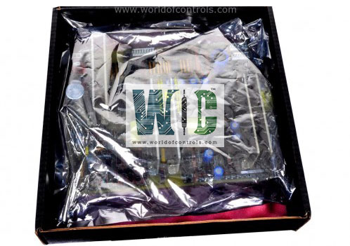
World Of Controls understands the criticality of your requirement and works towards reducing the lead time as much as possible.
IS230SNIDH1A - Isolated Digital DIN-Rail Module is available in stock which ships the same day.
IS230SNIDH1A - Isolated Digital DIN-Rail Module comes in UNUSED as well as REBUILT condition.
To avail our best deals for IS230SNIDH1A - Isolated Digital DIN-Rail Module, contact us and we will get back to you within 24 hours.
Part Number: IS230SNIDH1A
Manufacturer: General Electric
Series: Mark VIe
Product Type: Isolated Digital DIN-Rail Module
Availability: In Stock
Repair: 3-5 Days
Country of Manufacturer: United States (USA)
IS230SNIDH1A is an Isolated Digital DIN-Rail Module manufactured and designed by General Electric. It is a part of the Mark VIe Series used in GE Distributed Control Systems. The Mark VIe is controlled by a Windows 7 HMI. Your existing operator and maintenance stations will benefit from the most recent HMI/SCADA CIMPLICITY graphics system, which includes easy screen navigation, alarm/event management, and trending tools. Your Windows 7 HMIs can run GE's cyber security applications, which aid in providing security and compliance with current and emerging cyber security standards. The board is capable of processing logic functions and powering various functions within a system. It offers seamless interfacing capabilities with other boards, enhancing its adaptability within complex systems.
The LED indicators on the board's front panel, namely the Status and Fault LEDs, provide essential visual cues that play a pivotal role in monitoring the board's performance and diagnosing issues. To ensure effective board monitoring and troubleshooting, it's crucial to grasp the significance of these indicators and their various states.
The Status LED is an invaluable source of information about the board's current operational state. It communicates vital details through distinct illumination patterns:
Flashing Green (During Operation):
Solid Green (Board Stopped):
The Fault LED serves as a crucial early warning system, promptly alerting operators to the presence of anomalies or faults in the system. Understanding its behavior during fault occurrences and resets is essential for efficient troubleshooting:
Flashing Red (Fault Detected):
A flashing red Fault LED indicates that the board has detected a fault or anomaly in its operation.
This prompt visual cue serves as an immediate alert to operators, signaling the need for attention and investigation.
Faults can range from minor issues to critical malfunctions, and the flashing red light ensures that no potential problem goes unnoticed.
Solid Red (During Reset or Fault Acknowledgment):
When a fault is detected, the Fault LED may turn solid red during the fault acknowledgment or reset process.
This phase typically occurs after the fault has been addressed or when the system is actively working to resolve the issue.
The solid red light acts as a confirmation that the fault is being addressed and that corrective measures are underway.
The module under consideration incorporates a host of advanced features, making it an indispensable component in ensuring the robust and precise operation of the Distributed Control System (DCS). Here, we explore these features in depth:
The optional Process Data Highway (PDH) serves as a vital link between the CIMPLICITY HMI/data server and various remote components, including operator stations, printers, historians, and other customer computers. It's important to note that the PDH does not establish a direct connection with the Mark VIe control system; its primary role is to facilitate communication among these external devices.
WOC is happy to assist you with any of your automation requirements. For pricing and availability on any parts and repairs contact us.
What is IS230SNIDH1A?
It is a Isolated Digital DIN-Rail Module manufactured and designed by General Electric.
What operating system is used for the Mark VIe HMI?
The Mark VIe HMI runs on Windows 7, a widely used operating system that provides a user-friendly interface and efficient performance.
What is the CIMPLICITY graphics system?
CIMPLICITY is a SCADA (Supervisory Control and Data Acquisition) graphics system developed by General Electric that is used to create graphical displays for process monitoring and control. The system includes features such as easy screen navigation, alarm/event management, and trending tools.
What components can be found on the front faceplate?
The front faceplate of the board includes components such as LED indicators, connectors, diodes, capacitors, resistors, transistors, ferrite beads, integrated circuits, and resistor networks.
What are the two LED indicators on the board's front panel, and what do they signify?
The board's front panel features two LED indicators -Status and Fault. The Status LED indicates different operational states, including flashing green during operation and solid green when the board is stopped. The Fault LED provides information about fault occurrences or resets, aiding in board monitoring and troubleshooting.
What are the key features of the module?
Key features of the module include its ability to provide highly reliable and accurate digital input signals to the DCS, DIN-rail mounting design for easy installation, isolation capability to prevent interference between input signals, and a high-speed response time for rapid signal processing.
How does the Plant Data Highway (PDH) function within the system, and what is its primary role?
The optional Process Data Highway (PDH) serves as a link between the CIMPLICITY HMI/data server and various external components, such as operator stations, printers, historians, and customer computers. It's important to note that the PDH does not directly connect with the Mark VIe control system; its primary role is to facilitate communication among these external devices.
What are the benefits of the CIMPLICITY graphics system?
The CIMPLICITY graphics system provides a user-friendly interface that enables operators to quickly and easily navigate through the system, manage alarms and events, and monitor trends. These features help to improve the efficiency and effectiveness of the control system.