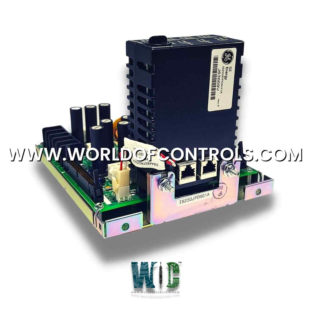
World Of Controls understands the criticality of your requirement and works towards reducing the lead time as much as possible.
IS230JPDMG1A - Power Distribution (JPDM) Board is available in stock which ships the same day.
IS230JPDMG1A - Power Distribution (JPDM) Board comes in UNUSED as well as REBUILT condition.
To avail our best deals for IS230JPDMG1A - Power Distribution (JPDM) Board, contact us and we will get back to you within 24 hours.
SPECIFICATIONS:
Part Number: IS230JPDMG1A
Manufacturer: General Electric
Series: Mark VIe
Product Type: Power Distribution (JPDM) Board
Number of channels: 12
Power supply voltage: 28 V dc
Voltage Range: 18 - 32 VDC
Maximum lead resistance: 15 Ω
Input span, transmitters: 1 - 5 V dc
Mounting: DIN-rail mounting
Isolation: 1500 V rms
Technology: Surface mount
Operating temperature: -30 to 65°C
Size: 15.9 cm high x 17.8 cm
Repair: 3-7 Day
Availability: In Stock
Country of Origin: United States
Manual: GEH-6721G
FUNCTIONAL DESCRIPTION:
IS230JPDMG1A is a Power Distribution (JPDM) Board manufactured and designed by General Electric as part of the Mark VIe Series used in GE Distributed Control Systems. The Power Distribution (JPDM) board receives 28 V dc input power from external ac/dc or dc/dc converters and distributes power to the control system. JPDM provides fuse protection for all outputs. JPDM integrates into the PDM system feedback through the PPDA I/O pack. JDPM is designed to maintain three separate power buses for R, S, and T applications. Jumpers can be used to provide a single bus with redundant supplies. Two adjacent JPDM boards can be wired together.
COMPATIBILITY:
The IS200JPDM board is compatible with the feedback signal P1/P2 connectors on JPDB, JPDF, and JPDE leading to a PPDA I/O pack. The DC-62 connector on JPDM is compatible with the IS220PPDA I/O pack.
INSTALLATION:
The JPDM is base-mounted vertically on a metal bracket in a cabinet used by the PDM. Refer to the wiring diagrams for power input and output. There is a 50-pin diagnostic connector, P1/P2, mounted on the top and bottom of the board.
OPERATION:
WOC has the largest stock of GE Distributed Turbine Control System Replacement Parts. We can also repair your faulty boards. WORLD OF CONTROLS can also supply unused and rebuilt backed-up with a warranty. Our team of experts is available round the clock to support your OEM needs. Our team of experts at WOC is happy to assist you with any of your automation requirements. For pricing and availability on any parts and repairs, kindly get in touch with our team by phone or email.
How is the JPDM Board installed within a turbine control system?
Installation involves mounting the JPDM Board in a secure and accessible location within the turbine control panel or enclosure. Proper wiring connections are made to ensure reliable power distribution to connected components. Adherence to safety guidelines and electrical codes is crucial during installation.
Can the JPDM Board be customized for specific turbine control system requirements?
Yes, JPDM Boards can be customized based on the specific needs and specifications of the turbine control system. Customizations may include the number and type of connections, voltage ratings, and additional safety features tailored to the application.
What maintenance procedures are recommended for the JPDM Board in a turbine control system?
Regular inspection of connections, circuitry, and protective devices is recommended to identify and address any issues promptly. Cleaning of contacts and periodic testing of circuit protection mechanisms are also essential to ensure optimal performance and safety.