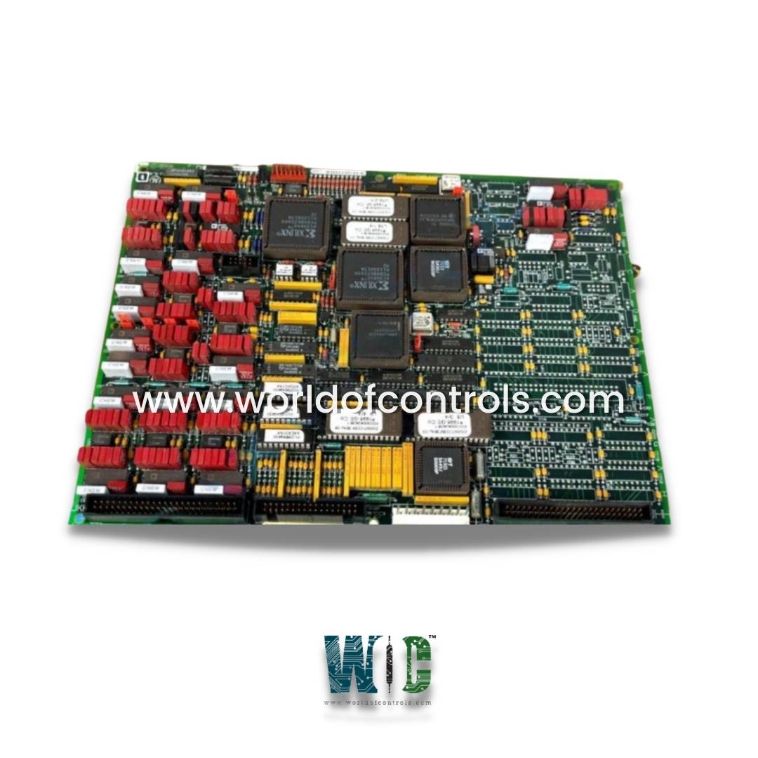
World Of Controls understands the criticality of your requirement and works towards reducing the lead time as much as possible.
DS215TCCBG3AZZ01A - VME Transmission Processor Board is available in stock which ships the same day.
DS215TCCBG3AZZ01A - VME Transmission Processor Board comes in UNUSED as well as REBUILT condition.
To avail our best deals for DS215TCCBG3AZZ01A - VME Transmission Processor Board, contact us and we will get back to you within 24 hours.
SPECIFICATIONS:
Part Number: DS215TCCBG3AZZ01A
Manufacturer: General Electric
Series: Mark V
Board Type: VME-based processor board
Function: Data transmission, communication, diagnostics
System Compatibility: GE Mark V / Mark VI / Mark VIe
Memory: SRAM and EPROM Communication Protocols
Processor: 32-bit microprocessor
Power Consumption: 10–15 Watts
Data Bus: VMEbus A24/A16
Operating Voltage: +5V DC
Board Dimensions: 6U VME
Size: 8.25 cm high x 4.18 cm
Repair: 3-7 Days
Availability: In Stock
Weight: 2.5 Kg
Country of Origin: United States
FUNCTIONAL DESCRIPTION:
DS215TCCBG3AZZ01A is a VME Transmission Processor Board manufactured and designed by General Electric as part of the Mark V Series used in GE Speedtronic Gas Turbine Control Systems. It interfaces with the TBCB terminal board, mounted on the R5 core, and the TCEB board located in the P1 core, to receive various types of analog signals. These include standard 4–20 mA and 0–1 mA current loop inputs commonly used for sensors such as pressure and temperature transmitters, as well as RTD (Resistance Temperature Detector) inputs, which require precise signal conditioning to convert resistance into accurate temperature values. Additionally, the TCCB handles generator and bus voltage inputs essential for electrical monitoring and synchronization, along with line current inputs necessary for power management and protection functions. Once these signals are received, the TCCB performs necessary scaling to bring them within acceptable input ranges, ensuring compatibility with downstream processing. The scaled and conditioned signals are then transmitted to the STCA (Signal Termination and Conditioning - Analog) board via the 3PL connector, where they are digitized and integrated into the control system. The TCCB significantly enhances the analog I/O capacity of the turbine control system, making it suitable for complex applications requiring extensive instrumentation and high-accuracy signal processing.
INSTALLATION:
The TCCB board is typically installed within the R5 or P1 core cabinet, depending on system configuration. It is mounted securely onto the designated card rack using appropriate mounting hardware to ensure proper grounding and physical stability. Prior to installation, ensure that the cabinet power is turned off to prevent electrical damage. Once the board is seated, carefully connect the ribbon cables or wiring harnesses from the TBCB and TCEB terminal boards to the corresponding connectors on the TCCB. Additionally, connect the 3PL cable from the TCCB to the STCA board to allow communication of the conditioned signals. All connections must be double-checked for correct alignment and firm seating. After confirming all connections, power can be restored to the system, and verification procedures, such as signal calibration and input validation, should be conducted to ensure proper operation. Proper labeling, grounding, and shielding of signal cables are also important to minimize noise and maintain signal integrity.
OPERATION:
The TCCB (Common Extended Analog I/O Board) functions as an intermediary between field instrumentation and the turbine control system, handling the reception, conditioning, and scaling of various analog signals. It continuously receives analog inputs from the TBCB and TCEB terminal boards, which may include 4-20 mA or 0-1 mA signals from pressure, temperature, or flow transmitters; RTD signals for temperature monitoring; and voltage and current inputs from generator and bus lines. The TCCB processes these signals by filtering and scaling them to standardized levels that can be accurately interpreted by the system.
Once conditioned, the analog signals are transmitted to the STCA board through the 3PL connector, where they are digitized and forwarded to the control processor for monitoring, protection, and control actions. The board operates continuously and automatically, with no manual intervention required during normal system runtime. Its reliable performance is critical for accurate signal acquisition, which directly affects the turbine's operational stability, efficiency, and protective functions. The TCCB also plays a key role in enabling diagnostic and alarm features by ensuring clean and precise analog signal input for further processing within the control system.
WOC offers the largest inventory of replacement parts for GE Speedtronic Gas Turbine Control Systems. We provide both unused and rebuilt boards backed by warranty as well as expert repair services for damaged units. Our team of professionals is available 24/7 to support all your OEM and automation requirements. For pricing and availability on components or repair services, please reach out to us via phone or email.
What is the primary function of the VME Transmission Processor Board?
The board handles data transmission, system communication, and synchronization within the GE turbine control system. It ensures seamless communication between the control processor and I/O modules or other system components.
What types of communication protocols are supported by this board?
The board supports ARCNET, Ethernet (optional), and serial interfaces like RS-232 and RS-485, depending on the system design and firmware.
What type of memory is used for firmware and data buffering on the board?
The board uses EPROM or flash memory for firmware storage and SRAM for temporary data buffering and processing.