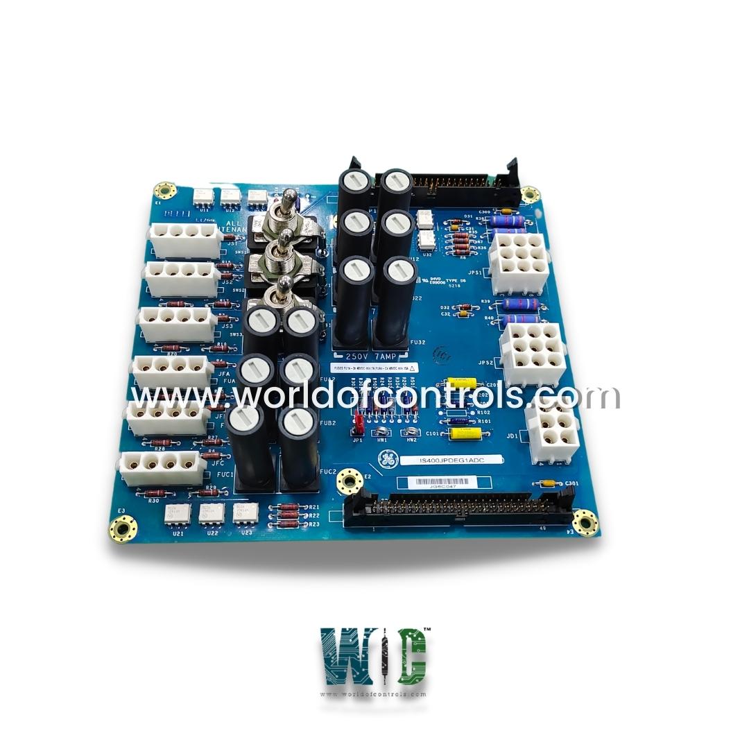
World Of Controls understands the criticality of your requirement and works towards reducing the lead time as much as possible.
IS400JPDEG1ADC - DC Battery Power Distribution Board is available in stock which ships the same day.
IS400JPDEG1ADC - DC Battery Power Distribution Board comes in UNUSED as well as REBUILT condition.
To avail our best deals for IS400JPDEG1ADC - DC Battery Power Distribution Board, contact us and we will get back to you within 24 hours.
SPECIFICATIONS
Part Number: IS400JPDEG1ADC
Manufacturer: General Electric
Series: Mark VIe DCS
Board Type: DC Battery Power Distribution Board
Input Voltage: 24 V DC / 48 V DC
Power Supply Inputs: 2
DC Bus Configuration: Floating
Feedback Interface: PPDA I/O pack
Compatibility: JPDB, JPDF, JPDS, JPDM (P1/P2 connectors)
Diagnostic Connectors: 50-pin
Board Size: 16.51 cm High x 17.8 cm
Operating Temperature: 0 to 45
Repair: 3-7 Days
Mounting: 6
Country of Origin: USA
Availability: In Stock
Manual: GEH-6721D
FUNCTIONAL DESCRIPTION
IS400JPDEG1ADC is a DC Battery Power Distribution Board manufactured and designed by General Electric as part of the Mark VIe Series used in distributed control systems. The dc power distribution board, IS200JPDE, receives dc power from a battery or power supplies and distributes it to terminal boards and other system loads. JPDE supports a floating dc bus that is centered on Earth using resistors and provides voltage feedback through PPDA to detect system ground faults. It provides inputs for two power supplies. JPDE is able to operate at either 24 V dc or 48 V dc. JPDE integrates into the PDM system feedback offered through the PPDA I/O pack. This board is limited by the current that can be passed through it using conventional board construction. JPDE does not supply power to bulk 500 W - 24 V input/28 V output power supplies providing I/O pack control power.
COMPATIBILITY:
The board is fully compatible with the feedback signal P1/P2 connectors found on the JPDB, JPDF, JPDS, and JPDM terminal boards. These connections enable the seamless transfer of feedback and monitoring signals between the power distribution circuitry and the PPDA I/O pack. When interconnected, this setup allows the PPDA pack to continuously monitor voltage levels, ground fault conditions, and system health status across the DC distribution network. This compatibility ensures reliable integration within the Mark VIe control system, supporting efficient power management and diagnostic capabilities.
INSTALLATION:
In a PDM-related cabinet, the JPDE board is vertically base-mounted on a metal bracket to ensure mechanical stability and proper ventilation. During installation, it is essential to follow the wiring diagrams provided in the system documentation to accurately route DC power input and output connections to the appropriate terminals. A 50-pin diagnostic connector is located on both the top and bottom of the board, providing access for system diagnostics, feedback monitoring, and maintenance checks.
JPDE I/O CHARACTERISTICS:
CONFIGURATION:
The JPDE board includes a jumper JP1 used to configure the grounding behavior of the DC power distribution system. When jumper JP1 is engaged, the JPDE provides local earth connections through a pair of 6 kΩ voltage-centering resistors connected between the positive and negative DC lines. This setup centers the floating DC bus around the earth ground, helping to stabilize voltage potential and enable effective ground fault detection. When JP1 is withdrawn, the ground connection is disabled, allowing the DC bus to remain completely floating.
WOC maintains the largest inventory of OEM replacement parts for GE Distributed Control Systems (DCS), including new, unused, rebuilt, and fully tested boards, all backed by a comprehensive warranty. We also offer expert repair and refurbishment services for faulty boards, ensuring reliable performance and minimal downtime. Our team of highly trained engineers is available 24/7 to provide technical support, troubleshooting, and guidance for all your automation and control system needs. For pricing, availability, or service inquiries, contact us by phone or email, and our experts will assist you in keeping your systems running smoothly and efficiently.
What is the primary function of the JPDE board?
The JPDE board distributes DC power from batteries or power supplies to terminal boards and system loads. It also provides feedback to the PPDA I/O pack for voltage monitoring and ground fault detection. This ensures reliable power management within the Mark VIe DCS.
What input voltages does the JPDE support?
The board operates at either 24 V DC or 48 V DC, depending on system requirements. It accepts two independent power supply inputs to maintain redundancy and continuous operation.
How does JPDE handle grounding?
When jumper JP1 is installed, the floating DC bus is centered on earth using 6 k Ohms voltage-centering resistors. Removing JP1 leaves the bus fully floating, allowing flexibility in system grounding.
Which terminal boards are compatible with JPDE?
JPDE is compatible with JPDB, JPDF, JPDS, and JPDM boards via the P1/P2 feedback connectors. These connections interface with the PPDA I/O pack for monitoring and diagnostics.