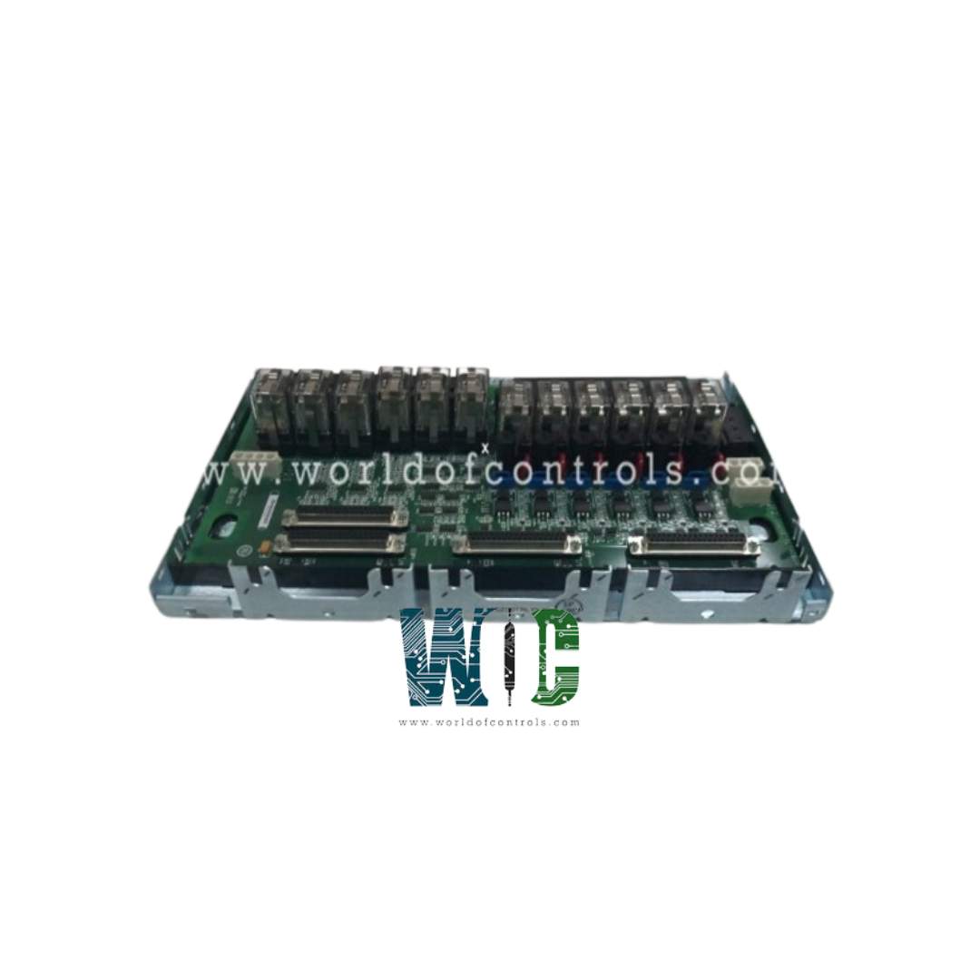
World Of Controls understands the criticality of your requirement and works towards reducing the lead time as much as possible.
IS230TRLYH2E - Relay Output Terminal Board is available in stock which ships the same day.
IS230TRLYH2E - Relay Output Terminal Board comes in UNUSED as well as REBUILT condition.
To avail our best deals for IS230TRLYH2E - Relay Output Terminal Board, contact us and we will get back to you within 24 hours.
SPECIFICATIONS:
Part Number: IS230TRLYH2E
Manufacturer: General Electric
Series: Mark VIe
Product Type: Relay Output Terminal Board
Number of channels: 12 channels
Rated voltage on relays: 100/125 V dc
Maximum Load Current: 5.0 A resistive
Input Isolation: 1500 V
AC Voltage Rejection: 60 V rms
Max response time on: 25 ms
Power supply current: 5 A dc
Technology: Surface mount
Measurement accuracy: 53 mV
Maximum Distance: 300 m
Operating temperature: -30 to 65ºC
Size: 17.8 cm wide x 33.02 cm high
Repair: 3-7 Days
Availability: In Stock
Country of Origin: United States
FUNCTIONAL DESCRIPTION:
IS230TRLYH2E is a Relay Output Terminal Board manufactured and designed by General Electric as part of the Mark VI Series used in GE Distributed Turbine Control Systems. The Relay Output with TMR contact voting (TRLYH2E) terminal board provides 12 contact-voted relay outputs. Each TMR section holds 12 sealed relays, for a total of 36. The relay contacts from R, S, and T are combined to form a voted Form A (NO) contact. 24/125 V dc or 115 V ac can be applied.
TRLYH2E does not have power distribution. For the Mark VI and VIe control systems, an optional power distribution board can be added so that a standard 125 V dc or 115 V ac source, or an optional 24 V dc source with individual fuses, can be provided for field solenoid power. WPDFH2A provides a single fuse in the high side (pin 1 of J1–J4) of each power distribution circuit for AC applications where a fuse in neutral return wire (pin 3 of J1–J4) is not desirable. TRLY2F is the same as TRLY1F except that the voted contacts form a Form B (NC) output. Both boards can be used in Class 1 Division 2 applications.
INSTALLATION:
Connect the wires for the 12 solenoids directly to two I/O terminal blocks on the terminal board. The TRLYH2E Terminal Board Wiring. Each block is held down with two screws and has 24 terminals accepting up to #12 AWG wires. A shield termination strip attached to chassis ground is located immediately to the left side of each terminal block. Solenoid power for outputs 1-12 is available if the WPDF daughterboard is used. Alternatively, customer power may be wired to the terminal block. The 28 V dc power for the terminal board relay coils and logic comes from the three I/O processors connected at JR1, JS1, and JT1.
OPERATION:
The 28 V dc power for the terminal board relay coils and logic comes from the three I/O processors connected at JR1, JS1, and JT1. The same relays are used for ac voltages and dc voltages, as specified in the Specifications section. TRLY1F and 2F use the same relays with differing circuits. Relay drivers are mounted on the TRLY1F and drive the relays at the frame rate.
This board only supports TMR applications. The relay control signals are routed into TRLY1F from the three I/O processors R, S, and T through plugs JR1, JS1, and JT1. These signals directly control the corresponding relay driver for each TMR section R, S, and T. Power for each section’s relay coils comes in from its own I/O processor and is not shared with the other sections.
TRLYH2E features TMR contact voting. The relay contacts from R, S, and T are combined to form a voted Form A (NO) contact. 24/125 V dc or 115 V ac can be applied. TRLY is the same except that the voted contacts form a Form B (NC) output. The following figure shows the TMR voting contact circuit.
WOC is proud to offer the largest stock of OEM Replacement parts for GE Distributed Turbine Control Systems, ensuring you have access to the critical components you need for maintenance, upgrades, or replacements. In addition to supplying genuine parts, we specialize in repairing faulty boards and providing unused and professionally rebuilt boards, all supported by a reliable warranty to guarantee performance and peace of mind. Our team of experts is available round the clock to offer technical guidance and solutions tailored to your automation and control system requirements. Committed to maximizing uptime and operational efficiency, we are always ready to assist with any OEM needs, from parts procurement to repairs. For pricing, availability, or support, please contact our team via phone or email at WOC. Your automation challenges are our top priority, and we are dedicated to delivering fast, reliable, and expert solutions.
What is the GE IS230TRLYH2E?
The IS230TRLYH2E is a 12-channel Relay Output Terminal Board from GE’s Mark VIe Series, designed for turbine control and industrial automation systems. It provides TMR contact-voted relay outputs, ensuring high reliability. Each TMR section has 12 sealed relays, combining signals from three processors (R, S, T) to form a voted output.
How does TMR contact voting work on this board?
TMR (Triple Modular Redundancy) voting combines signals from three independent I/O processors. Only the majority vote activates the relay output, minimizing the risk of faults. This ensures reliable operation in critical turbine or industrial control systems.
What are the electrical specifications of this board?
The board operates at 100/125 V dc with a maximum load current of 5 A resistive. It supports 24/125 V dc or 115 V ac applications. The input isolation is 1500 V, and it provides accurate relay switching with a response time of 25 ms.