SPECIFICATIONS
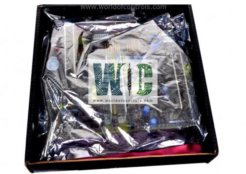
Part No.: IS230SRTDH1A
Manufacturer: General Electric
Country of Manufacture: United States of America (USA)
Number of channels: 8
Span: 0.3532 to 4.054 V
Maximum lead resistance: 15 ohm
Product Type: RTD Terminal Board
Availability: In Stock
Series: Mark VIe
Functional Description
IS230SRTDH1A is an RTD Terminal Board developed by GE. It is a part of Mark VIe control system. The board serves as a compact and versatile solution for integrating RTD inputs within control system setups. The board is designed to be compact, making it suitable for installation in a wide range of environments. It offers flexibility in mounting options, allowing it to be mounted on either a DIN rail or a flat surface. This versatility ensures that the board can be easily integrated into different control system configurations.
Product Features
- RTD Sensor Connectivity: Equipped with eight RTD input channels, each designed to receive 2-wire, 3-wire, or 4-wire RTD connections. This configuration enables accurate temperature measurement by compensating for lead-wire resistance—essential in high-precision applications such as generator stator winding monitoring, bearing temperature detection, and other thermally sensitive industrial processes.
- High-Density Euro-Style Terminal Blocks: Each RTD input is interfaced through Euro-block terminal connectors, which are directly mounted on the PCB. These high-density terminal blocks provide:
- Secure mechanical connections.
- Low-resistance contact surfaces for improved signal integrity.
- Simplified field wiring during installation or replacement cycles.
- The terminals support stranded or solid conductors and accommodate field wiring sizes commonly used in industrial environments.
- On-Board Identification Chip: The board includes an on-board ID PROM chip,
- Communicates the board type, serial number, and hardware revision to the I/O processor.
- Facilitates system-level diagnostics and automatic configuration recognition by the Mark VIe controller.
- Enables faster commissioning and replacement by reducing manual intervention and errors during hardware identification.
- This electronic ID system is particularly advantageous in systems where modular replacement is common, as it ensures compatibility and traceability.
- Compatibility with PRTD and VRTD I/O Packs. Designed to interface with either:
- PRTD (Programmable RTD) I/O Packs, or VRTD (Voltage-based RTD) I/O Packs.
- The selection depends on the processing methodology and signal conditioning approach required by the application. The connection to the I/O pack is facilitated via a ribbon cable, ensuring minimal signal degradation and high-speed data acquisition. These I/O packs handle A/D conversion, linearization, filtering, and transmission of the temperature data to the Mark VIe controller.
- Physical Design and Mounting
- Form Factor: Compact and optimized for control cabinet layouts with limited space.
- Mounting Options: Can be mounted via DIN rail clips or through direct panel mounting holes, enabling integration into various industrial setups.
- Environmental Compatibility: Designed with industrial-grade materials to withstand thermal variations, vibration, and electrical noise typically found in power generation environments.
Installation Guidelines
- Mounting Options: The board, along with a plastic insulator, mounts onto a sheet metal carrier, which is then installed on a DIN rail. Alternatively, the SRTD and insulator can be mounted directly onto a sheet metal assembly, which is secured within the control cabinet using bolts. This mounting flexibility accommodates different installation configurations and ensures secure placement of the SRTD board within the control system setup.
- Terminal Block Connection: Features a Euro-style box-type terminal block with 36 terminals, providing a reliable connection interface for wiring the eight RTDs directly. These terminals are designed to accommodate typically #18 AWG wires, which are commonly shielded twisted triplets. This wiring configuration ensures stable and consistent signal transmission between the RTDs and the board, enabling accurate temperature measurement and monitoring.
- Shield Terminal Strip: Please note that this design does not include a shield terminal strip. However, if shielded cables are used, the shield terminal connection can be established using an external mounting bracket supplied by GE or the customer. This ensures proper grounding and shielding of the cables, minimizing electromagnetic interference and maintaining signal integrity.
- Chassis Ground Connection: Terminals 25 through 34 on the Euro-style terminal block are not connected and are typically left unused. Additionally, terminals E1 and E2 serve as mounting holes for the chassis ground screw connection (SCOM). Proper grounding of the SRTD board is essential for electrical safety and system performance.
The WOC team is always available to help you with your Mark VIe requirements. For more information, please contact WOC.
Frequently Asked Questions
What is IS230SRTDH1A?
It is an RTD Terminal Board developed by GE under the Mark VIe series.
How are system limits monitored for each RTD input on the SRTD board?
Each RTD input with system limit checking based on configurable high and low levels. These limits can be adjusted to generate alarms when exceeded and can be configured for enable/disable and latching/non-latching behavior. The RESET SYS signal is used to reset out-of-limit signals. In Triple Modular Redundancy (TMR) systems, limit logic signals are voted, and the resulting composite diagnostic is available in each controller.
How is the resistance of each RTD checked for accuracy on the board?
The resistance of each RTD connected is continuously monitored and compared with the correct value. If the resistance deviates significantly from the expected range (either too high or too low), a fault is generated, indicating a potential issue with the RTD sensor.
How does the board ensure proper identification and compatibility with the I/O processor?
Each connector on the board is equipped with its ID device, which is interrogated by the I/O processor board. This ID device contains essential information, including the terminal board serial number, board type, revision number, and connector location. If a mismatch is detected between the ID information and the expected configuration, a hardware incompatibility fault is triggered, alerting operators to potential issues with board compatibility.
