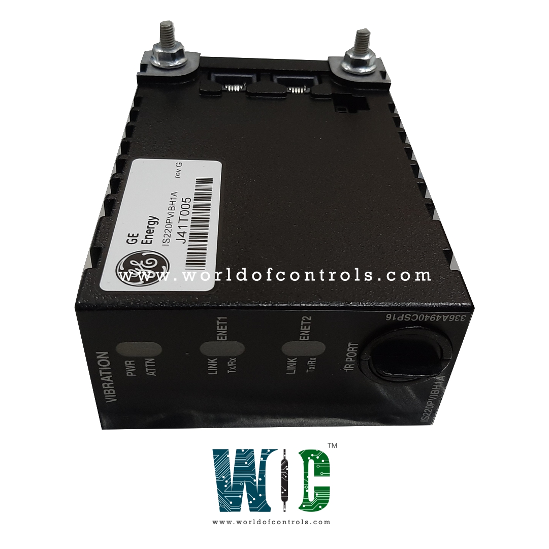
World Of Controls understands the criticality of your requirement and works towards reducing the lead time as much as possible.
IS220PVIBH1A, REV C - Vibration Monitor Board is available in stock which ships the same day.
IS220PVIBH1A, REV C - Vibration Monitor Board comes in UNUSED as well as REBUILT condition.
To avail our best deals for IS220PVIBH1A, REV C - Vibration Monitor Board, contact us and we will get back to you within 24 hours.
SPECIFICATIONS:
Part Number: IS220PVIBH1A, REV C
Manufacturer: General Electric
Series: Mark VIe
Function: Vibration Monitor Board
Number of Channels: 12
Thermocouple Types: E, J, K, S
Common Mode Voltage: +5 Volts
Normal Mode Rejection: 250 mV
Operating temperature: -30 to 65 °C
Size: 8.26 cm wide x 4.19 cm
Technology: Surface Mount
Repair: 3-7 days
Availability: In Stock
Country of Origin: United States
Manual: GEH-6721G
FUNCTIONAL DESCRIPTION:
IS220PVIBH1A, REV C is a Vibration Monitor Board manufactured and designed by General Electric as part of the Mark VIe Series used in GE Distributed Control Systems. The Vibration Monitor (PVIB) pack is designed to serve as the electrical interface between one or two I/O Ethernet networks and the TVBA vibration terminal board. It is built with a processor board common to all Mark* VIe distributed I/O packs, and it also includes an acquisition board and a daughterboard to handle signal processing and communication tasks.
The PVIB pack is responsible for collecting vibration or proximity data from various sensors. Channels 1 through 8 support inputs from multiple sensor types, including Proximitors, Velomitor, seismics, and integrated-output accelerometers (only on channels 1 to 3). Channels 9 through 12 are dedicated solely to Proximitor sensors, while channel 13 is configurable to accept either a Keyphasor signal or a proximity-type input, offering flexibility in monitoring machine shaft dynamics or position.
For connectivity, the PVIB pack uses dual RJ45 Ethernet connectors for network communication and a 3-pin input for power. It supports both single and dual Ethernet network configurations. Dual networks are used when frame rates are lower than 100 Hz, whereas single networks accommodate standard frame rates such as 3.125, 6.25, 12.5, 25, 50, and 100 Hz, depending on the application’s requirements.
Data output from the PVIB is routed through a DC-37 connector, which links directly to the associated terminal board. The unit is equipped with LED indicators to assist with visual diagnostics, making troubleshooting easier for technicians. Additionally, an infrared port is available for local serial communication, allowing for efficient maintenance and configuration without disrupting normal operations.
INSTALLATION:
OPERATION:
The processor board interfaces with an acquisition board tailored to the specific function of the I/O pack. When input power is applied, the soft-start circuit gradually increases the voltage supplied to the processor board. This triggers the sequencing of local power supplies and removes the processor reset. The processor then runs self-test routines before loading the application code, which is stored in flash memory, and is specific to the I/O pack type.
The application code verifies board compatibility by reading the board ID to confirm that the application code, acquisition board, and terminal board match correctly. Once a successful match is confirmed, the processor initiates Ethernet communication by requesting a network address using the Dynamic Host Configuration Protocol (DHCP) and the unique identification from the terminal board.
WOC has the largest stock of GE Distributed Control System Replacement Parts. We can also supply unused and rebuilt backup with a warranty. Our team of experts is available around the clock to support your OEM needs. Our team of experts at WOC is happy to assist you with any of your automation requirements. For pricing and availability on any parts and repairs, kindly get in touch with our team by phone or email.
How does the Vibration Monitor Board optimize data accuracy in challenging environments?
The Vibration Monitor Board is specifically designed to operate accurately in environments with high mechanical stress, electrical noise, and temperature variations. It utilizes advanced signal filtering algorithms to isolate meaningful vibration data from external noise, ensuring that the measurements remain precise even under disruptive conditions.
What are the benefits of advanced signal processing in vibration monitoring?
The Vibration Monitor Board employs advanced signal processing techniques such as the Fourier Transform and Fast Fourier Transform (FFT) to analyze vibration data more accurately. By converting the data from the time domain to the frequency domain, these techniques allow for the identification of specific faults like misalignments, bearing defects, and imbalances.
What are the common features of a vibration monitor board?
Features often include real-time monitoring, multiple sensor inputs, signal conditioning, filtering, threshold detection, alarm outputs, and communication interfaces like 4- 20mA, Modbus, or RS485.