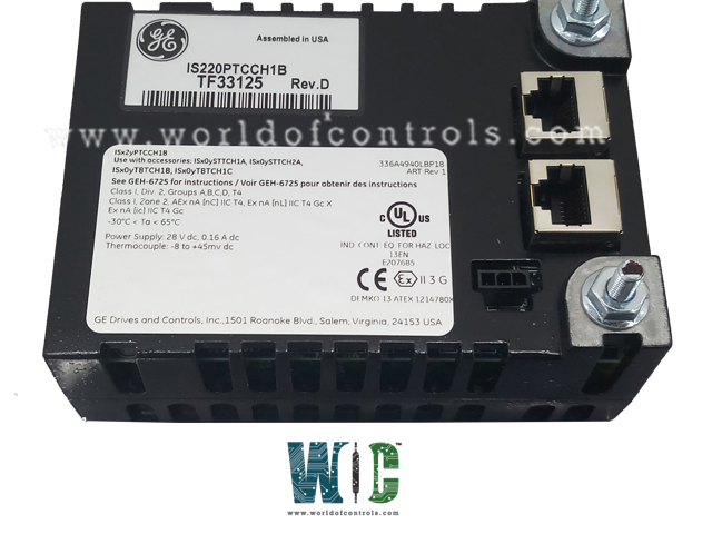
World Of Controls understands the criticality of your requirement and works towards reducing the lead time as much as possible.
IS220PTCCH1B, REV D - Thermocouple Input Module is available in stock which ships the same day.
IS220PTCCH1B, REV D - Thermocouple Input Module comes in UNUSED as well as REBUILT condition.
To avail our best deals for IS220PTCCH1B, REV D - Thermocouple Input Module, contact us and we will get back to you within 24 hours.
SPECIFICATIONS:
Part Number: IS220PTCCH1B, REV D
Manufacturer: General Electric
Series: Mark VIe
Function: Thermocouple Input Module
Number of Channels: 12
Thermocouple Types: E, J, K, S
Span: -8 mV to +45 mV
A/D Converter: 16-bit
Common Mode Voltage: +5 Volts
Normal Mode Rejection: 250mV
Microprocessor: AMD-K6 300 MHz
Operating temperature: -30 to 65� C
Size: 8.26 cm wide x 4.19 cm
Technology: Surface Mount
Repair: 3-7 Day
Availability: In Stock
Country of Origin: United States
Manual: GEH-6721_VOL_II
�
FUNCTIONAL DESCRIPTION:
IS220PTCCH1B, REV D is a Thermocouple Input Module manufactured and designed by General Electric as part of the Mark VIe Series used in GE Distributed Control Systems. The PTCC functions as the electrical interface between one or two I/O Ethernet networks and a thermocouple input terminal board. It comprises a processor board, which is shared across all Mark VIe distributed I/O packs and an acquisition board dedicated to thermocouple input. The pack supports up to 12 thermocouple inputs, and with two packs, it can manage up to 24 inputs on the TBTCH1C. In a TMR configuration with the TBTCH1B terminal board, three packs are required, each with its cold junction, supporting a total of 12 thermocouples. The pack receives input through dual RJ45 Ethernet connectors and a three-pin power input. The output is provided through a DC-37 pin connector, which connects directly to the terminal board. Visual diagnostics are shown via LEDs, and local diagnostics can be accessed through an infrared port.
INSTALLATION:
OPERATION:
ANALOG INPUT HARDWARE:
The PTCC input board receives 12 millivolt-level signals from the thermocouples connected to the terminal board. The analog input system includes six differential multiplexers, a main multiplexer, and a 16-bit analog-to-digital converter that transmits the digital data to the processor board. Each input is equipped with hardware and firmware filters, and the converter samples at a rate of up to 120 Hz.
POWER MANAGEMENT:
The PTCC includes power management in the 28 V input circuit. The management function provides a soft start to control current inrush during power application. After applying power, the circuit provides a fast current limit function to prevent a pack or terminal board failure from propagating back onto the 28 V power system. The green PWR indicator will light when power is present and working properly. If the current limit function operates, the indicator will be out until the problem is cleared.
WOC has the largest stock of Replacement Parts for GE Distributed Turbine Control Systems. We can also repair your faulty boards and supply unused and rebuilt boards backed up with a warranty. Our team of experts is available round the clock to support your OEM needs. Our team of experts at WOC is happy to assist you with any of your automation requirements. For pricing and availability on parts and repairs, kindly contact our team by phone or email.
What is the power supply requirement for the module?
The module receives power through a three-pin input connector and includes a built-in soft-start feature to manage current inrush. It operates with a 28 V input circuit.
How do I connect the Ethernet cables to the module?
You can connect one or two Ethernet cables, depending on the system configuration. The pack works with either Ethernet port, but for twin connections, it is common practice to link ENET1 to the network associated with the R controller.
How is the module protected from power issues?
The module includes a power management system with a current limit function to prevent failures from affecting the 28 V power system. The green PWR indicator will light when power is stable, and if the current limit is triggered, the indicator will go out until the issue is resolved.