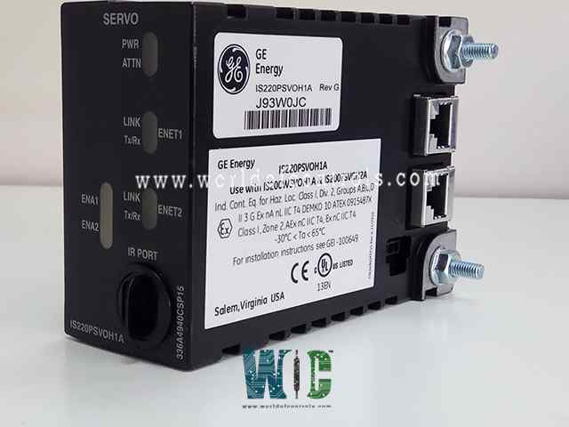
World Of Controls understands the criticality of your requirement and works towards reducing the lead time as much as possible.
IS220PSVOH1A, REV G - Servo Control I/O Module is available in stock which ships the same day.
IS220PSVOH1A, REV G - Servo Control I/O Module comes in UNUSED as well as REBUILT condition.
To avail our best deals for IS220PSVOH1A, REV G - Servo Control I/O Module, contact us and we will get back to you within 24 hours.
SPECIFICATIONS:
Part Number: IS220PSVOH1A, REV G
Manufacturer: General Electric
Product Type: Servo Control I/O Module
Function: I/O Module
Series: Mark VIe
Number of outputs: 2
Power supply voltage Nominal: 28 V DC
Pulse rate accuracy: 0.05%
Magnetic PR pickup signal generates: 150 V
Operating temperature: -30 to +65°C
Size: 8.26 cm high x 4.19 cm
Input Filter: Hardware Filter, 4 ms
Technology: Surface-mount
Availability: In Stock
Weight: 0.8kg
Repair: 3-7 days
Country of Origin: USA
Manual: GEH-6721D
FUNCTIONAL DESCRIPTION:
IS220PSVOH1A, REV G is a Servo Control I/O Module manufactured and designed by General Electric as part of the Mark VIe Series used in GE Distributed Turbine Control Systems. The PSVO I/O pack serves as the electrical interface between one or two I/O Ethernet networks and a TSVO servo terminal board. It includes a processor board used across all Mark VIe distributed I/O packs, along with a specialized I/O board designed specifically for servo functions. This pack works in conjunction with the adjacent WSVO servo driver module to manage two servo valve position loops, offering a choice of five output current levels ranging from 10 to 120 mA DC. It provides LVDT excitation, supports up to eight LVDT feedback inputs, and accepts two pulse rate inputs from fuel flow meters. Inputs are received via dual RJ45 Ethernet ports, while 28 V DC power is supplied from the terminal board. Outputs are delivered through a DC-62 pin connector, which links directly to the terminal board. For diagnostics, the pack features LED indicators for visual status and includes an infrared port for local diagnostic serial communication.
POWER MANAGEMENT:
The PSVO includes power management in the 28 V input circuit. The management function provides a soft start to control current inrush during power application. After applying power, the circuit provides a fast current limit function to prevent a pack or terminal board failure from propagating back onto the 28 V power system. When power is present and working properly, the green PWR indicator will light. If the current limit function is operating, the indicator will remain out until the problem is cleared.
INSTALLATION:
OPERATIONS:
The processor board interfaces with an acquisition board that is specifically designed for the I/O pack's function. When power is applied, a soft-start circuit gradually increases the voltage to the processor board. This triggers the activation of local power supplies and releases the processor from reset. The processor then performs self-diagnostic tests and loads the appropriate application code from its onboard flash memory, which is specific to the I/O pack type. It checks the board ID to confirm compatibility between the application code, acquisition board, and terminal board. Once a correct match is verified, the processor uses the terminal board’s unique identification to request a network address via DHCP. After successfully initializing the Ethernet connection, it programs the onboard logic, begins executing the application, and enables the acquisition board to start operation.
WOC holds one of the largest inventories of GE Distributed Control System (DCS) replacement parts, offering both unused and professionally rebuilt components backed by a comprehensive warranty to ensure reliability and performance. Our team of experienced engineers and technicians is available 24/7 to support your OEM and automation requirements, including troubleshooting, repairs, system upgrades, and technical consultations. Whether you need a single spare part or a complete control solution, WOC provides prompt service, expert guidance, and fast delivery to minimize downtime and maintain operational efficiency. For pricing and availability on parts or repairs, please contact our team by phone or email.
What is the primary function of the Servo Control I/O Module (PSVO)?
The PSVO module serves as the interface between Ethernet-based I/O networks and the TSVO servo terminal board. It controls servo valve positioning, provides LVDT excitation, receives LVDT feedback, and interfaces with fuel flow meters.
What types of servo valve output currents are supported?
The module supports five selectable DC output current ranges for servo valve control, ranging from 10 mA to 120 mA.
How are the modules mounted and secured?
PSVO packs are directly plugged into the terminal board and mechanically secured using threaded inserts and a mounting bracket. The bracket must be adjusted to avoid lateral force on the DC-62 connector.