World Of Controls understands the criticality of your requirement and works towards reducing the lead time as much as possible.
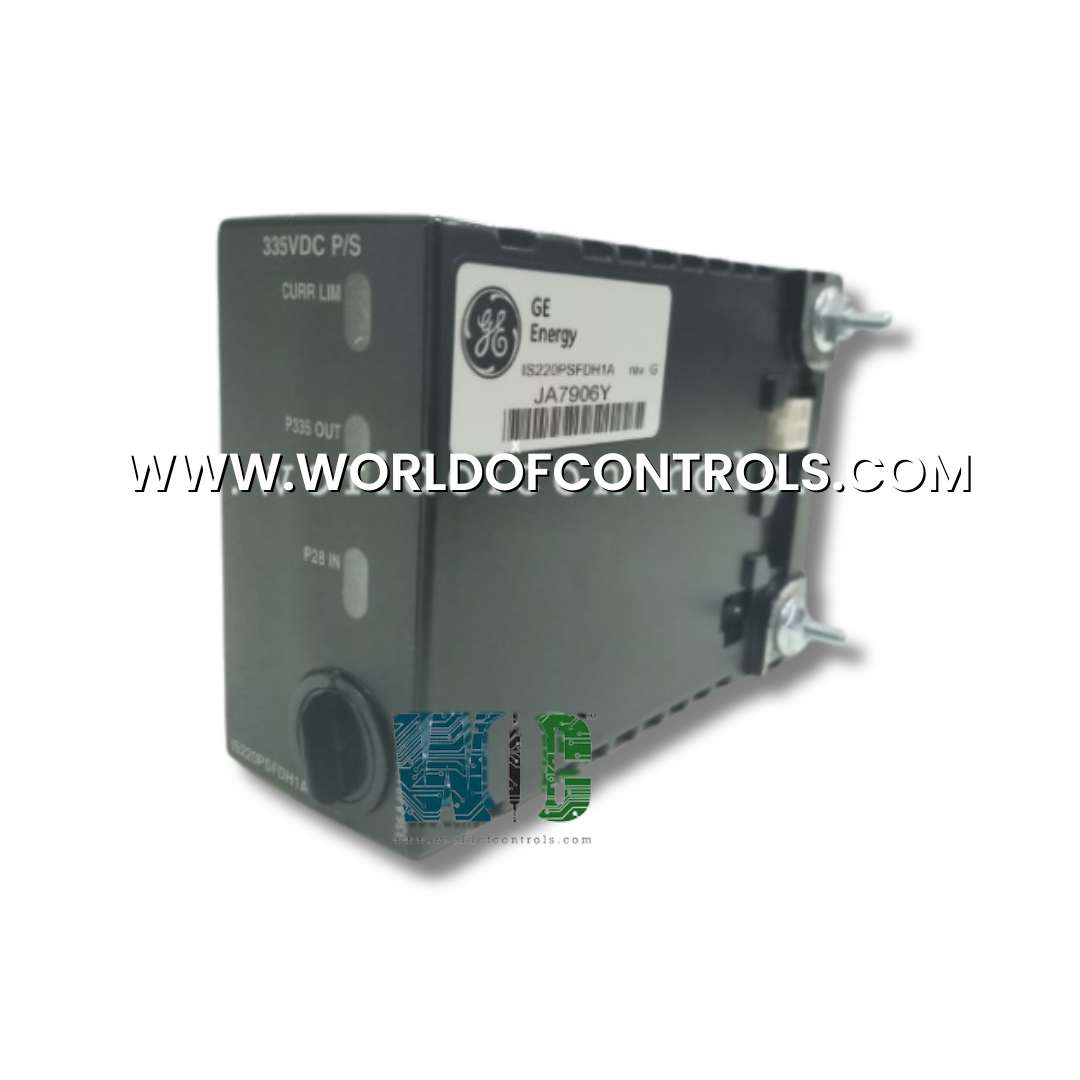
IS220PSFDH1A, REV A - Flame Detector Power Supply Module is available in stock which ships the same day.
IS220PSFDH1A, REV A - Flame Detector Power Supply Module comes in UNUSED as well as REBUILT condition.
To avail our best deals for IS220PSFDH1A, REV A - Flame Detector Power Supply Module, contact us and we will get back to you within 24 hours.
SPECIFICATIONS:
Part Number: IS220PSFDH1A, REV A
Manufacturer: General Electric
Series: Mark VIe
Product Type: Flame Detector Power Supply Module
Maximum Input Voltage: 29.4 V dc
Inrush current limit: 550 mA for 40 μS,
Input current at full load, 28 V dc: 137 mA
Start-up time at full load, 28 V dc: 34 mS
Output short circuit current limit with self-recovery: 7 mA
Input current ripple at full load, 28 V dc: 66 mA
Power consumption at full load, 28 V dc: 4.1 W
Typical output ripple at full load: 520 mV
Efficiency at full load: 40%
Power supply voltage: 125 V dc
Voltage Range: 18 - 32 VDC
Mounting: DIN-rail mounting
Technology: Surface mount
Operating temperature: -30 to 65°C
Size: 8.26 cm high x 4.19 cm wide
Repair: 3-7 Days
Availability: In Stock
Country of Origin: United States
Manual: GEH-6721D
FUNCTIONAL DESCRIPTION:
IS220PSFDH1A, REV A is a Flame Detector Power Supply Module manufactured and designed by General Electric as part of the Mark VIe Series used in GE Distributed Gas Turbine Control Systems. The flame detector power supply (PSFD) is housed within an I/O pack enclosure and is typically installed above the primary gas turbine trip protection (TRPG) terminal board. It receives its input from a 28 V DC source provided by the power distribution board (JPDL) and delivers a high-voltage output rated at 335 V DC with a current of 5 mA. In the system, three separate PSFD units are connected to the TRPG via terminals J3, J4, and J5 in a diode-ored, Triple Modular Redundancy (TMR) configuration, allowing them to supply power to up to eight flame detectors collectively. This configuration ensures maximum reliability, as each power supply is capable of independently powering all eight detectors if the other two units fail, thereby maintaining continuous flame detection and turbine safety. The main features of the pack include:
COMPATIBILITY:
The Power Supply for Flame Detector (PSFD) provides reliable power to the flame detection circuitry within the Turbine Trip Protection (TRPG) system. It delivers a stable output to the TRPG through connectors J3, J4, and J5, which are typically diode-ored to ensure redundancy and uninterrupted operation. This configuration allows the flame detector to remain functional even if one power path experiences a fault, ensuring continuous monitoring of combustion.
The PSFD is usually mounted on a sheet metal platform above the TRPG terminal board, allowing easy access for installation and maintenance. This elevated placement helps with heat dissipation, reduces exposure to mechanical vibrations, and minimizes interference with other control modules. By supplying dedicated and stable power, the PSFD is critical for turbine safety, enabling prompt detection of abnormal flame conditions and triggering protective actions through the TRPG system.
INSTALLATION:
OPERATIONS:
The PSFD converts 28 V DC input into a 335 V DC output. The input is current-limited, hot-swap compatible, and transformer-isolated from the floating output. The power conversion uses a non-regulated, fixed-ratio push-pull switching topology. Both input and output are current-limited, with the input also supporting hot-swapping. The output voltage can be monitored locally through a differential pair of test points, attenuated 100:1 for safe measurement. The input and output LEDs do not indicate a specific voltage level and simply indicate the presence of input or output voltage. Similarly, the current limit LED is for indication only and does not provide a measurement of the over current magnitude. The current limit LED is in series with the signal path for the activation signal. In the event that the current limit LEDs fails open, a circuit bypasses the LED, and the limiter continues to function. The PSFD also features three status LEDs to indicate operational conditions.
WOC holds the largest inventory of OEM replacement parts for GE Distributed Control Systems, ensuring that clients can quickly access the components they need to maintain and optimize their operations. In addition to supplying unused parts, we also offer expertly rebuilt boards and provide reliable repair services for faulty or damaged units, all of which come with a warranty for added peace of mind. Our dedicated team of automation and OEM specialists is available around the clock, ready to provide technical support, guidance, and solutions for any control system requirement. Whether you need immediate parts, expert repairs, or advice on system integration, WOC is committed to delivering prompt, professional assistance. For detailed information on pricing, availability, or repair services, clients are encouraged to contact our team directly by phone or email to receive personalized support.
What is a Flame Detector Power Supply (PSFD) Module?
The PSFD module provides a dedicated power source to the flame detection circuitry in turbine protection systems, ensuring reliable operation and uninterrupted monitoring of combustion.
What input and output voltages does the PSFD support?
The module converts a 28 V DC input to a 335 V DC output. The input is current-limited, hot-swap compatible, and transformer-isolated from the floating output.
How is the PSFD installed?
The PSFD is typically mounted above the TRPG on a sheet metal plate connected to chassis ground (FE). It is mechanically secured using threaded studs that slide into mounting brackets.
How do I connect the PSFD to the TRPG?
The 335 V DC output is connected via the PSFD’s 2x2 connector P2 to TRPG connectors J3, J4, or J5. The 28 V DC input is applied through the 1x3 connector P1, which supports soft-start to control inrush current.