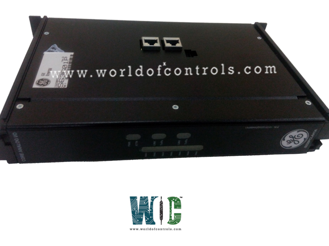
World Of Controls understands the criticality of your requirement and works towards reducing the lead time as much as possible.
IS220PCLAH1A - Core Analog I/O Module is available in stock which ships the same day.
IS220PCLAH1A - Core Analog I/O Module comes in UNUSED as well as REBUILT condition.
To avail our best deals for IS220PCLAH1A - Core Analog I/O Module, contact us and we will get back to you within 24 hours.
TECHNICAL SPECIFICATIONS:
Part Number: IS220PCLAH1A
Manufacturer: General Electric (GE)
Series: Mark VIe
Functional Acronym: PCLA
Product Type: Core Analog I/O Module
Number of Channels: 4 channels
A/D Converter Resolution: 16-bit
Number of channels Simplex
Power Supply Input Voltage: 28 V DC Nominal
Power Consumption: 19.8 W max
Thermocouple Interface Capacity: Supports up to 8 channels
RTD Interface Capacity: Supports up to 8 channels
Current Loop Type: 4-20 mA input and output
Status Diagnostics: 4 onboard Status LEDs
Compliance Voltage: 18 V dc
Redundancy Configurations: Simplex and Triple Modular Redundant (TMR) layouts
Ambient Operating Temperature: -30°C to +65°C -22°F to +149°F
Repair Lead Time: 3–7 Business Days
Availability: In Stock
Country of Origin: United States
Manual Reference: GEH-6721_Vol_III_BQ
The IS220PCLAH1A is a Core Analog I/O Module designed and manufactured by General Electric for the high-performance Speedtronic Mark VIe Distributed Control System platform. The Core Analog I/O for aeroderivative gas turbines (PCLA) and associated Core Analog (SCLS and SCLT) terminal boards provide a large portion of the analog signal I/O required to operate an engine. PCLAH1A and SCLT provide thermocouple inputs, RTD inputs, voltage inputs, and 4-20 mA current loop inputs and outputs. PCLA can be applied in simplex controller simplex I/O, dual controller simplex I/O, dual controller TMR I/O, and TMR controller TMR I/O control systems. A single SCLT terminal board fans signal inputs to one or three connected PCLA(s). PCLA provides the electrical interface between one or two Ethernet I/O networks and the terminal board. Inside the PCLA module is a BCLA acquisition board and a BPPx processor board. Input to the PCLAH1A module is through dual RJ-45 Ethernet connectors and a 28 V dc power connector, P1. Field device I/O is connected through 72 Euro-style box-type terminal blocks on the SCLS edge and is connected through 48 Euro-style box-type terminal blocks on the SCLT edge. Connection to SCLS is through 96-pin J3 and 48-pin J4 connectors on SCLS. The connection between SCLS and SCLT is through one 68-pin cable on the J2 connector on SCLS, and the JR/JS/JT connector on SCLT.
COMPATIBILITY:
The PCLAH1A includes one of the compatible processor boards. The PCLAH1A is equipped with a BPPB processor board, while the PCLAH1B uses a functionally compatible BPPC processor board that is supported with the ControlST software suite V04.03 and higher. The PCLA module is fully compatible with other Mark VIe control system I/O packs and controllers. It is designed to operate at frame rates of 10, 20, 40, 80, 160, and 320 ms, and it supports various frame rates, redundancy options, and networking configurations as specified in the relevant system table.
INSTALLATION:
THERMOCOUPLES:
The PCLAH1A supports E, J, K, S, and T types of thermocouples. Simplex inputs from the field are terminated on SCLS. There are eight simplex thermocouple inputs. TMR inputs from the field are terminated on SCLT and then fanned out to three PCLA modules. There are eight fanned (TMR) thermocouple inputs. The PCLA input board accepts 16 (8 each from SCLS and SCLT) signals at mV levels from the thermocouples wired to the terminal board. The thermocouple input section consists of differential multiplexers, amplifier gain stages, a main multiplexer, and a 16-bit analog-to-digital converter that sends the digital data to the adjacent processor board. Each input has hardware filters, and the converter samples at up to 120 Hz. Thermocouples can be grounded or ungrounded. Thermocouples can be located up to 300 meters (984 feet) from the turbine I/O cabinet with a maximum two-way cable resistance of 450 Ohms. Linearization for individual thermocouple types is performed by the PCLA.
A single cold junction is provided with each SCLS board. Three cold junctions, one for each PCLA, are provided on SCLT. The module accepts a controller backup cold junction value, CJBackup, in the event a problem is detected with the local sensor. The PCLA may be configured to use a controller-provided remote cold junction value, CJRemote. All thermocouple inputs are biased with a DC voltage that will drive the temperature signal full scale negative if an open wire occurs. There is a configuration to report an open thermocouple as fail cold or fail hot. Measurement accuracy for the thermocouple is 0.1% full scale, or 53 uV excluding the cold junction reading.
ANALOG VOLTAGE OR CURRENT INPUTS:
The inputs can be configured as current or voltage inputs using jumpers (JP#A) on SCLS or SCLT. The PCLA accepts input voltage signals from the terminal board, four input channels from SCLS, and four input channels from SCLT. The analog input section consists of analog multiplexer blocks, several gain and scaling selections, and a 16-bit analog-to-digital converter. The inputs can be individually configured as ±5 Vor ±10 V scale signals or 4-20 mA, depending on the input configuration. The terminal board provides a 250 Ω burden resistor when configured for current inputs, yielding a 5 V signal at 20 mA. These analog input signals are first passed through a passive, low-pass filter network with a pole at 75.15 Hz. The measurement accuracy offered by PCLA is 0.1% of the full scale over the operating temperature range. The inputs can be configured as current or voltage inputs using jumpers (JP#A) on the terminal boards SCLA/SCLT. The JP#A jumper removes the 250 Ω burden resistor for voltage input applications. Each input has one more jumper (JP#B) on the board that is used to determine if the return terminal is grounded or floating.
WHY PARTNER WITH WORLD OF CONTROLS
World of Controls specializes in supplying high-quality, warranty-backed OEM replacement parts, including unused surplus and professionally rebuilt components for critical turbine control and industrial automation systems like the General Electric Mark VIe platform. To minimize customer downtime and ensure original equipment standard compliance, every component undergoes rigorous inspection, testing, and verification in an advanced electronics lab. Beyond parts distribution, the company delivers comprehensive, global support through 24/7 technical assistance, expert troubleshooting, component repair services, and rapid shipping, ensuring optimal efficiency and long-term reliability for critical industrial operations worldwide.
What is GE IS220PCLAH1A?
It is a high-performance Core Analog I/O Module manufactured by General Electric for the Speedtronic Mark VIe control platform. It serves as a centralized telemetry processor that handles thermocouples, RTDs, voltage, and 4–20 mA loop processing to operate aero-derivative gas turbines.
What is the primary function of the Core Analog I/O Module?
It is a Mark VIe Series Core Analog I/O Module designed to provide the large portion of analog signal I/O (such as thermocouples, RTDs, and 4–20 mA loops) needed to manage aeroderivative gas turbines.
What type of resolution does the onboard converter provide?
The PCLA module utilizes a high-precision 16-bit analog-to-digital (A/D) converter for processing field inputs with a measurement accuracy of 0.1% full scale.
What happens if a thermocouple wire breaks during operation?
All thermocouple inputs are biased with an internal DC voltage that drives the temperature signal full-scale negative if an open wire occurs, which can be configured to report as fail cold or fail hot.
How is a channel toggled between voltage and current loop modes?
Channels are individually configured using JP#A jumpers on the terminal boards; applying the jumper removes a 250 Ohms burden resistor for voltage inputs, while leaving it in place supports 4-20 mA current loops.