World Of Controls understands the criticality of your requirement and works towards reducing the lead time as much as possible.
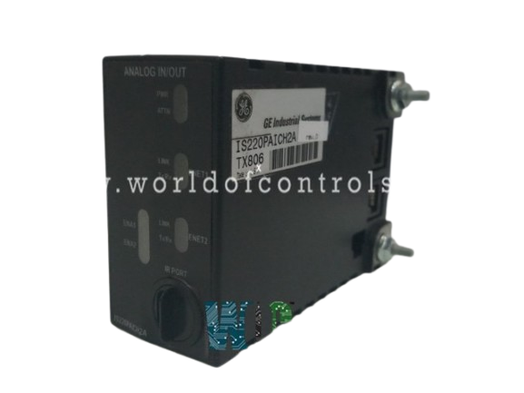
IS220PAICH2A, REV D - Analog Input/Output Module is available in stock which ships the same day.
IS220PAICH2A, REV D - Analog Input/Output Module comes in UNUSED as well as REBUILT condition.
To avail our best deals for IS220PAICH2A, REV D - Analog Input/Output Module, contact us and we will get back to you within 24 hours.
SPECIFICATIONS:
Part Number: IS220PAICH2A, REV D
Manufacturer: General Electric
Series: Mark VIe
Product Type: Analog Input/Output Module
Number of channels: 12
Input Span: 1 - 5 V dc
Input COnverter Resolution: 16-bit
Power supply voltage: 28 V dc
Voltage Range: 14 to 32 V dc
Output Load: 800 Ohm for 4 - 20 mA
Mounting: DIN-rail mounting
Technology: Surface mount
Operating temperature: -30 to 65°C
Size: 8.26 cm high x 4.19 cm
Repair: 3-7 Days
Availability: In Stock
Country of Origin: United States
Manual: GEH-6721_Vol_II V
FUNCTIONAL DESCRIPTION:
IS220PAICH2A, REV D is an Analog Input/Output Module manufactured and designed by General Electric as part of the Mark VIe Series used in GE Distributed Turbine Control Systems. The Analog I/O Pack (PAIC) serves as the electrical interface for one or two I/O Ethernet networks and an analog input terminal board. It includes a BPPx processor and an acquisition board designed for analog input functions. The pack supports up to 10 analog inputs: the first eight can be set as ±5 V, ±10 V, or 4-20 mA current loop inputs, while the last two can be configured as ±1 mA or 4-20 mA current inputs.
Current loop input resistors are on the terminal board, where the PAIC senses voltage across them. The PAICH2 model supports two 0-20 mA current loop outputs, while the PAICH2 adds hardware for 0-200 mA current on the first output. The I/O pack receives input via dual RJ-45 Ethernet connectors and a three-pin power input. Output is managed through a DC-37 pin connector linked to the terminal board. Indicator LEDs provide visual diagnostics.
COMPATIBILITY:
The PAIC I/O pack features one of several compatible BPPx processor boards. The PAICH1A and H2A models incorporate a BPPB processor, while the PAICH1B and H2B use a functionally equivalent BPPC, which is supported in the ControlST* software suite V04.03 and later. Additionally, the PAICH2A and H2B include extra hardware to enable 0-200 mA current on the first output, enhancing their capability for applications requiring higher current output.
Designed for seamless integration, the PAIC is compatible with the analog input terminal board (TBAIH1C) and the STAI board but does not support the DIN rail-mounted DTAI board. It exclusively works with the HIC version of TBAI, ensuring optimal performance and system stability. If connected to an older board revision, the PAIC will detect a compatibility issue and generate an alert, but no physical damage will occur if powered on in error.
INSTALLATION:
Securely mount the desired terminal board. Directly plug the PAIC I/O pack into the terminal board connectors. Mechanically secure the I/O pack(s) using the threaded studs adjacent to the Ethernet ports. The studs slide into a mounting bracket specific to the terminal board type. The bracket location should be adjusted such that there is no right-angle force applied to the DC-37 pin connector between the I/O pack and the terminal board. The adjustment should only be required once in the service life of the product. Plug in one or two Ethernet cables, depending on the system configuration. The I/O pack will operate over either port. If dual connections are used, the standard practice is to connect ENET1 to the network associated with the R controller. Apply power to the I/O pack by plugging in the connector on the side of the pack. It is not necessary to remove power from the cable before plugging it in because the I/O pack has inherent soft-start capability that controls current inrush on power application.
CONNECTORS:
The I/O pack features a DC-37 pin connector on its underside, which directly interfaces with the discrete input terminal board. This connector transmits 24 input signals, an ID signal, relay coil power, and a feedback multiplex command, ensuring seamless data and power transfer. Additionally, the I/O pack is equipped with two RJ-45 Ethernet connectors on its side. The primary system interface, labeled ENET1, serves as the main communication link, while the secondary connector, ENET2, provides redundancy for enhanced reliability. For power supply, a 3-pin connector on the side of the I/O pack delivers 28V DC to both the I/O pack and the terminal board, ensuring stable operation.
DIAGNOSTICS:
WOC offers the largest inventory of OEM Replacement Parts for GE Distributed Control Systems. In addition to supplying unused and rebuilt boards with a warranty, we also provide repair services for faulty boards. Our team of experts is available 24/7 to support your OEM needs and assist with any automation requirements. For pricing and availability on parts and repairs, please contact us by phone or email.
What are the signal types supported by Analog I/O modules?
Analog I/O modules typically support voltage signals (e.g., 0-10V, ±10V) and current signals (e.g., 4-20mA, 0-20mA). These modules convert analog signals from sensors or transmit analog signals to actuators based on system requirements.
What are the common types of Analog Input/Output Modules?
Common types include voltage input modules (0-10V), current input modules (4-20mA), and voltage or current output modules. These modules interface with sensors and actuators that require voltage or current signals for measurement and control.
What is the difference between Digital and Analog I/O Modules?
Digital I/O modules handle discrete signals (on/off), suitable for binary control tasks, while Analog I/O modules manage continuous signals, offering finer control over parameters like temperature, pressure, and flow in automation systems.