World Of Controls understands the criticality of your requirement and works towards reducing the lead time as much as possible.
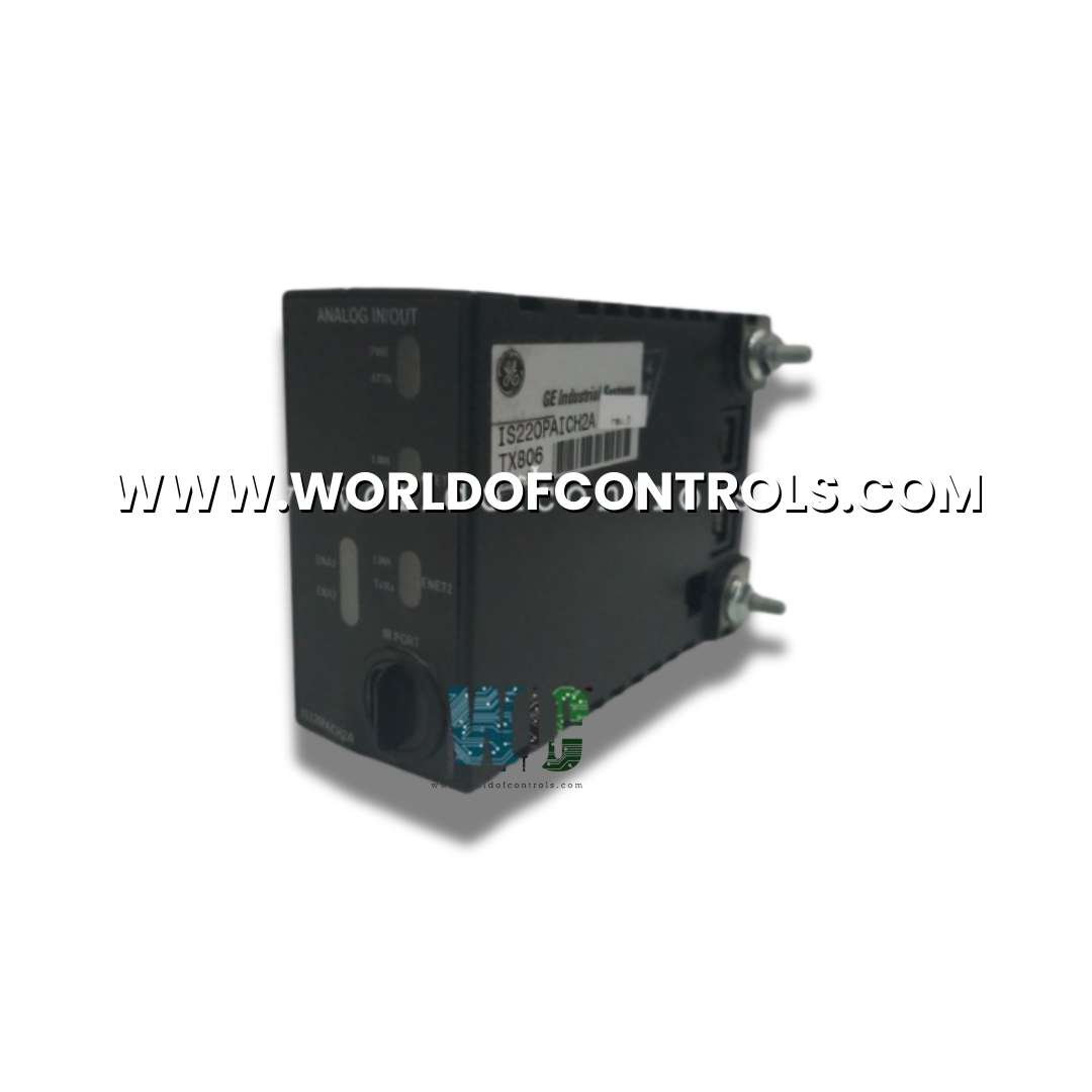
IS220PAICH2A, REV C - Analog Input/Output Module is available in stock which ships the same day.
IS220PAICH2A, REV C - Analog Input/Output Module comes in UNUSED as well as REBUILT condition.
To avail our best deals for IS220PAICH2A, REV C - Analog Input/Output Module, contact us and we will get back to you within 24 hours.
SPECIFICATIONS:
Part Number: IS220PAICH2A, REV C
Manufacturer: General Electric
Series: Mark VIe
Product Type: Analog Input/Output Module
Number of channels: 12
Input Span: 1 - 5 V dc
Input COnverter Resolution: 16-bit
Scan Time: 5ms
Power supply voltage: 28 V dc
Voltage Range: 14 to 32 V dc
Output Load: 800 Ohm for 4 - 20 mA
Mounting: DIN-rail mounting
Technology: Surface mount
Operating temperature: -30 to 65°C
Size: 8.26 cm high x 4.19 cm
Repair: 3-7 Day
Availability: In Stock
Country of Origin: United States
Manual: GEH-6721_Vol_II
FUNCTIONAL DESCRIPTION:
IS220PAICH2A, REV C is an Analog Input/Output Module manufactured and designed by General Electric as part of the Mark VIe Series used in GE Distributed Turbine Control Systems. The Analog I/O pack (PAIC) provides the electrical interface between one or two I/O Ethernet networks and an analog input terminal board. The PAIC contains a BPPX processor board and an acquisition board specific to the analog input function. The I/O pack is capable of handling up to 10 analog inputs, the first eight of which can be configured as +5 V or +10 V inputs, or 4-20 mA current loop inputs. The last two inputs may be configured as ±1 mA or 4-20 mA current inputs.
The load terminal resistors for current loop inputs are located on the terminal board and voltage is sensed across these resistors by the PAIC. The PAICHI also includes support for two 0-20 mA current loop outputs. The PAICH2 includes extra hardware to support 0-200 mA current on the first output. Input to the I/O pack is through dual RJ-45 Ethernet connectors and a three-pin power input. Output is through a DC-37 pin connector that connects directly with the associated terminal board connector. Visual diagnostics are provided through indicator LEDs.
COMPATIBILITY:
INSTALLATION:
CONNECTORS:
WOC has the largest stock of OEM Replacement Parts for GE Distributed Control Systems. We can also repair your faulty boards and supply unused and rebuilt boards backed up with a warranty. Our team of experts is available round the clock to support your OEM needs. Our team of experts at WOC is happy to assist you with any of your automation requirements. For pricing and availability on parts and repairs, kindly contact our team by phone or email.
What power supply is required for an Analog I/O module?
Most analog I/O modules operate on a 24V DC power supply, although the exact voltage requirements depend on the specific model. Some industrial-grade modules may support a wider voltage range for flexible deployment in different control systems.
What is the difference between unipolar and bipolar analog inputs?
Unipolar inputs handle signals that range from 0 to a positive maximum voltage (e.g., 0-10V or 0-20mA), meaning the signal always remains positive. Bipolar inputs, on the other hand, allow both positive and negative signal ranges (e.g., ±10V), making them suitable for applications requiring symmetrical signal variations, such as AC signal measurements or differential pressure sensing.
What is signal-to-noise ratio (SNR), and how does it impact Analog Input performance?
SNR represents the ratio of the desired signal strength to background noise, typically measured in decibels (dB). A higher SNR indicates cleaner signal acquisition, leading to more accurate data processing. Factors affecting SNR include shielding, grounding, and the quality of analog-to-digital conversion in the module.