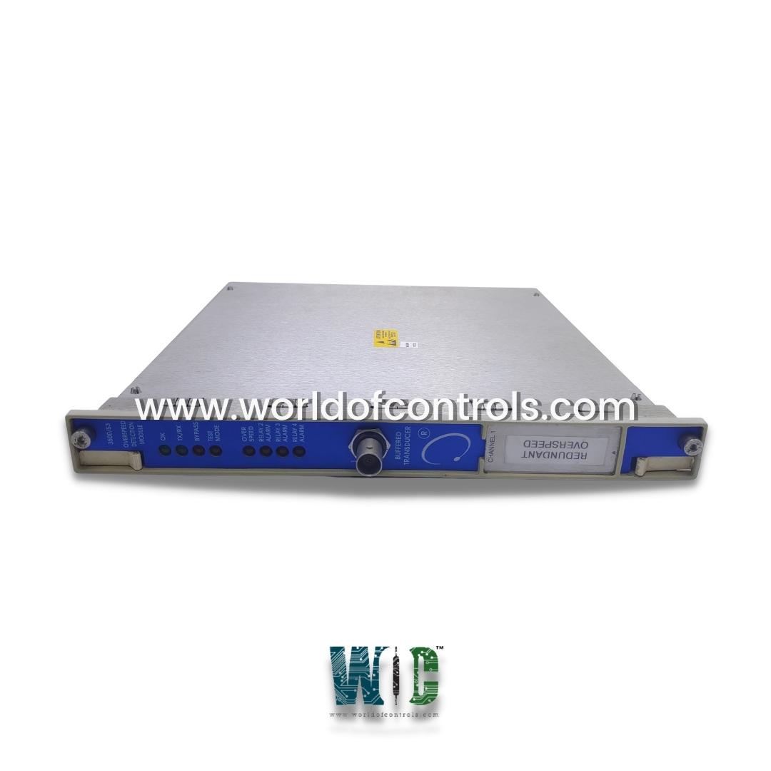
SPECIFICATIONS
Part Number: 3500/53
Manufacturer: Bently Nevada
Series: 3500
Operating Temperature: -30 to +65 degrees Celsius
Storage Temperature: -40 to +85 degrees Celsius
Humidity: 95%, non-condensing
Product type: Electronic Overspeed Detection System
Availability: In Stock
Country of Manufacture: United States (USA)
Functional Description
3500/53 is a Electronic Overspeed Detection System designed and developed by Bently Nevada. The Bently Nevada Electronic Overspeed Detection System for the 3500 Series Machinery Detection System is a highly reliable, quick response, redundant tachometer system designed for use as part of an overspeed protection system. It is intended to meet the overspeed protection requirements of American Petroleum Institute (API) Standards 670 and 612. The modules can be combined to form a 2-out-of-2 or 2-out-of-3 voting system (recommended). A 3500 rack with redundant power supplies is required for the Overspeed Detection System.
Input
- Signal:A single transducer signal from a proximity probe transducer or magnetic pickup is accepted by each Overspeed Detection module. The input signal has a voltage range of +10.0 V to -24.0 V. Signals that exceed this range are internally limited by the module.
- Input Impedance: 20 k ohm.
- Power Consumption: 8.0 watts, typical.
- Transducers: Bently Nevada 3300 8 mm Proximitor 3300 16 mm HTPS, 7200 5 mm, 8 mm, 11 mm, and 14 mm Proximitor; 3300 RAM Proximitor, or Magnetic pickups.
Alarms
- This setpoint is particularly significant in scenarios where rapid rotational acceleration could result in hazardous overspeed conditions. By setting this Danger setpoint, operators preemptively safeguard against potential equipment failure, breakdowns, and, most importantly, any risks to personnel safety.
- Configuration through Software: The adaptability and precision of the Module's alarm system are further underscored by its software-based configuration. Through the power of software, users can fine-tune and customize alarm parameters based on the specific operational characteristics of the machinery being monitored. This flexibility ensures that the alarm thresholds are aligned with the unique requirements of each application.
- Adjustable Alarm Range: One of the hallmark features of the Module's alarm system is its adjustable nature. Users have the freedom to set alarm thresholds that span the entire spectrum of the module's full-scale speed range. This dynamic range can typically be calibrated from 0 to 100% of the full-scale speed range, offering granular control over alarm triggers to suit diverse operational demands.
- Alarm Time Delays: Timing is of the essence in monitoring systems, and the Module's alarm system addresses this through rapid response. Alarms are accompanied by a time delay mechanism that ensures swift and accurate notifications. Specifically, when operating at speeds above 300 Hz, the time delay is less than 30 ms. This lightning-quick response time is instrumental in preventing potential issues from escalating into critical failures, thus minimizing downtime and optimizing operational continuity.
Transducer Conditioning
- Auto Threshold: Use for any input above 0.0167 Hz (1 revolution per event). The minimum triggering signal amplitude is 1 volt peak-to-peak.
- Manual Threshold: Selectable by the user from +9.9 Vdc to -23.9 Vdc. The minimum triggering signal amplitude is 500 millivolts peak-to-peak.
- Hysteresis: 0.2 to 2.5 volts, user selectable.
Front Panel LEDs
- OK LED: It serves as a reassuring beacon of proper functionality. When illuminated, this LED indicates that the Module is operating as intended and is in a healthy operational state. Its illumination provides operators and maintenance personnel with the initial confirmation that the module is ready to execute its monitoring tasks effectively.
- TX/XR LED: Signifies the communication status with other modules housed within the 3500 rack system. When active, this LED illuminates to indicate that the module is successfully establishing communication links with its peers in the rack. This communication is vital for the holistic monitoring and data sharing that the system facilitates.
- Bypass LED: It is a visual indicator of the module's operational mode. When activated, this LED is illuminated, signaling that the Module is in Bypass Mode. Bypass Mode might be engaged during certain maintenance or troubleshooting scenarios, allowing for temporary disengagement from the monitoring process while still maintaining overall system functionality.
- Test Mode LED: Serves as a prompt regarding the testing status. When this LED is illuminated, it signifies that the module has been put into Test Mode. Test Mode often involves simulating various conditions to ensure the responsiveness of the module and the overall monitoring system without affecting actual machinery operations.
- Alarm LEDs: A series of Alarm LEDs are integral to alerting operators about alarm conditions. Each of these LEDs corresponds to a specific relay and indicates that an alarm condition has been detected by the module. When illuminated, these LEDs provide a direct visual cue that specific monitoring parameters have exceeded set thresholds, indicating the need for immediate attention and potential maintenance intervention.
WOC is happy to assist you with any of your Bently Nevada requirements. Please contact us by phone or email for pricing and availability on any parts and repairs.
FREQUENTLY ASKED QUESTIONS
What is 3500/53?
It is a tachometer system designed to detect overspeed conditions in machinery and provide quick response and redundant protection. It is designed and developed by Bently Nevada and is intended to meet the overspeed protection requirements of American Petroleum Institute (API) Standards 670 and 612.
What is the recommended configuration?
Bently Nevada recommends configuring with a 2-out-of-2 or 2-out-of-3 voting system for redundant protection.
What type of machinery can this tachometer protect?
It can be used with a wide range of machinery, including turbines, compressors, pumps, generators, and motors.
What is required for installation?
A 3500 rack with redundant power supplies is required for the Overspeed Detection System.
What are the benefits?
Provides quick response and redundant protection against overspeed conditions, helping to prevent damage to machinery and reduce downtime. It is designed to meet industry standards and is highly reliable.
