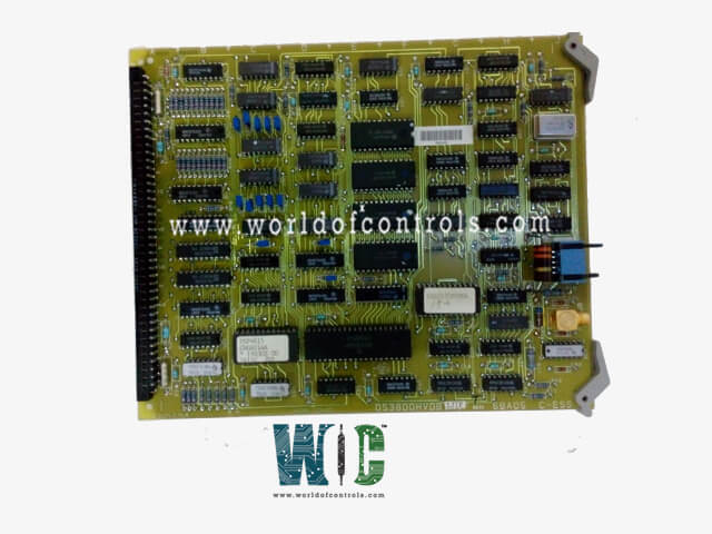
World Of Controls understands the criticality of your requirement and works towards reducing the lead time as much as possible.
DS3800HVDB1K - Video Driver Board is available in stock which ships the same day.
DS3800HVDB1K - Video Driver Board comes in UNUSED as well as REBUILT condition.
To avail our best deals for DS3800HVDB1K - Video Driver Board, contact us and we will get back to you within 24 hours.
Part No.: DS3800HVDB1K
Manufacturer: General Electric
Country of Manufacture: United States of America (USA)
Product Type: Video Driver Board
Availability: In Stock
Series: Mark IV
DS3800HVDB1K is a Video Driver Board developed by GE. It is a part of the Mark IV control system. It provides video signal processing and driving visual outputs for system monitoring. With features like the modular connector, retention levers, and secure 20-pin connector, the board ensures reliable and stable video connections. Its EPROM modules and jumpers enable easy configuration for optimal performance in turbine control applications. Proper handling and installation of the ribbon cable are essential to maintain signal integrity and avoid potential damage to the board.
Features a modular connector on one end of the board and retention levers on the other end. This design ensures the board's stable integration into the control system while minimizing the risk of damage or accidental disconnection.
The 20-pin connector is a feature that allows the operator to connect a ribbon cable after the board has been installed into the system, ensuring that the connection process is safe and minimizes the risk of damage.
Equipped with EPROM modules and 15 configurable jumpers that play important roles in configuring the board for specific operational requirements.
The 20-pin connector is specifically designed to reduce the risk of strain and damage to the ribbon cable during installation. It is recommended to connect the ribbon cable after the board is installed, to minimize the possibility of damaging the connections.
The WOC team is always available to help you with your Mark IV requirements. For more information, please contact WOC.
What is DS3800HVDB1K?
It is a Video Driver Board developed by GE under the Mark IV series.
How do the retention latches on the 20-pin connector work?
The retention latches are designed to keep the ribbon cable securely attached to the 20-pin connector. Once the cable is inserted, the latch swings over the connector and locks it in place. To remove the cable, simply disengage the latch by lifting it off the tab and then pull the connector out.
How do I handle the EPROM modules and jumpers?
The EPROM modules store the data and configuration settings for the board. The 15 jumpers are used for configuring the board's settings, such as operational parameters for video signal processing. When handling the board, ensure to follow the proper installation procedures and avoid unnecessary handling of the EPROM modules to prevent static damage.