SPECIFICATIONS
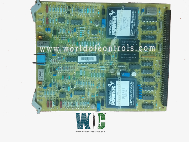
Part No.: DS3800HCVA1J
Manufacturer: General Electric
Country of Manufacture: United States(USA)
Product Type: Analog Output Board
Series: Mark IV
The DS3800HCVA1J is a Analog Output Board under the Mark IV series. It is a part of General Electric's Speedtronic series of products.
Features
- The Output Board has a modular connector for connecting to a drive and retention levers to keep the board in place. The board also has 14 jumpers and two amber indicator LEDs. The board also has three connectors accessible from the front and four trimmer resistors.
- Trimmer resistors are also known as trimpots. This is due to the fact that they have an adjustment screw and are potentiometers. The screws change the resistance provided by the component. Adjustment can be performed by a qualified servicer. To monitor the voltage while adjusting the screw, the servicer must have a full-featured testing device. Once the proper adjustment has been made, cover the screw with a few drops of a liquid that hardens quickly and prevents the screw from moving.
- The liquid is harmless to the components and can be peeled off to allow a servicer to make additional adjustments. This could happen if the board is installed in another drive or if the drive is upgraded with new components.
- Never force the board into the rack or the retention levers to move. Reposition the board over the modular connector and gently press down if it does not easily slide into the rack.
- The modular connector will slide into the matching connector in the rack if properly aligned.
- When you turn on the drive, the LEDs on the board will light up for a few seconds. This is a test to ensure that the LEDs are working properly.
DS3800HCVA1J Service Display
Each HCVA card outputs two analog signals. The output signal, which is determined by the position of the Berg jumpers, can range from 0 to 10 VDC or 4 to 20 ma. Perform the following tests on each HCVA card in R, S, and T. The HCVA cards in R, S, and T slots 1E and 2F are "optional."
- Before performing this test, ensure that the turbine is turned off.
- Check that the Berg jumpers are in the proper positions for the test.
- On HSAA cards, the Berg jumpers can be set to the positions specified in the Elementary.
- All other cards and modules' Berg jumpers should be set to the positions specified in the Elementary.
- In Data List 1C, change the scale to "Hardware Units."
- Enter the HCVA Service Display "forcing" mode by touching the membrane switches "DATA," "1," "4", and "ENTER."
- The 'REQUEST FORCE' soft switch.
"ENTER" and the User ID Code
- Refer to the Berg jumper listing for the HCVA card to determine whether the two channels are configured for voltage or current mode.
- The data in the following table for expected results are determined by the mode (voltage or current).
- Check that the Berg jumper positions for mode selection on the HCVA card match the Berg jumper positions for mode selection on.
-
- If the HCVA card is in voltage mode, the load resistor should be connected (i.e., the Berg jumpers should be set to "B").
- If the HCVA card is operating in the current mode, the load resistor should not be connected (i.e., the Berg jumpers should be set to "BLANK".
- When the HCVA card is operated in voltage mode and the load resistor is not connected (i.e., in current mode), the output increases to positive saturation. When the protection circuitry detects saturation, it deactivates the output relay. After a few seconds, the card attempts to reset itself. The output increases, and the output relay de-energizes once more. This cycle will last forever and should be avoided.
- Connect a meter across the output terminals of the HCVA channel under test.
-
- If the HCVA channel is in current mode, use an ammeter.
- If the HCVA channel is in voltage mode, use a voltmeter.
- Selects the HCVA channel under test.
- Press the "RAISE" and "LOWER" soft switches to set GSADJ to the desired values.
- Check to make sure the meter readings and CRT data are within the tolerances.
- If the card is in R, S, or T, make sure the red "TEST" LED on the HMPJ card is turned on.
- Check that the C sections running LED on the auxiliary display is turned on if the card is in C. This means that the analog outputs are turned on. If the appropriate LED is not "on," the HSAA card is prevented from producing the output voltage used as the test signal.
- Check the Berg jumpers' positions.
- Replace the HCVA card that is being tested.
The most extensive collection of GE Speedtronic Mark IV control components can be found at World of Controls. Our experts are available to assist you with your OEM requirements at any time. If you require any additional information, please contact WOC as soon as possible.
Frequently Asked Questions
What is DS3800HCVA1J?
The DS3800HCVA1J is a Analog Output Board under the Mark IV series.
How to Obtain this board?
World of Controls provides Mark IV as well as other OEM turbine control products. Contact WOC.
