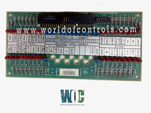
World Of Controls understands the criticality of your requirement and works towards reducing the lead time as much as possible.
DS3800DSQD1A - Sequencer Auxiliary Indicator Board is available in stock which ships the same day.
DS3800DSQD1A - Sequencer Auxiliary Indicator Board comes in UNUSED as well as REBUILT condition.
To avail our best deals for DS3800DSQD1A - Sequencer Auxiliary Indicator Board, contact us and we will get back to you within 24 hours.
SPECIFICATIONS:
Part Number: DS3800DSQD1A
Manufacturer: General Electric
Series: Mark IV
Product Type: Sequencer Auxiliary Indicator Board
Input Signal Voltage Levels: 0 V (Logic 0), +5 V DC (Logic 1)
Output Signal Voltage Levels: 0 V (Logic Low), +5 V DC (Logic High)
Logic Family Used: TTL / CMOS
Typical Propagation Delay: 15–25 ns
LED Forward Voltage: 2.0 V ± 0.2 V
LED Operating Current: 10–15 mA
Power Supply Requirement: +5 V DC ± 0.25 V
Maximum Power Dissipation: 5 W
Operating Temperature: 0 °C to +60 °C
Board Input Voltage Supply: +5 V DC ± 0.25 V
Board Size: 16.51 cm high x 17.8 cm
Repair: 3-7 Days
Country of Origin: USA
Availability: In Stock
Status: Discontinued by Manufacturer
FUNCTIONAL DESCRIPTION:
DS3800DSQD1A is a Sequencer Auxiliary Indicator Board manufactured and designed by General Electric as part of the Mark IV Series used in Speedtronic control systems. It is a logic-based sequencer board used in the GE Mark IV Speedtronic system to manage turbine auxiliary sequencing and provide step indication. It incorporates TTL/CMOS logic ICs, resistor networks, buffers, and diagnostic LEDs to process discrete input signals and deliver controlled logic outputs to turbine actuators and relays. The board is conformal coated for electrical isolation and environmental durability, and its modular design enables direct integration into the Mark IV backplane.
OPERATION:
The board executes programmed sequencing logic by validating field inputs and propagating outputs in the correct order for startup, synchronization, loading, shutdown, and protective trips. LEDs map to internal logic nodes, providing a direct view of sequence states, while test points enable scope-based verification of signals. In redundant Mark IV configurations, the board operates in parallel across master and slave channels, ensuring uninterrupted sequencing if one path fails.
COMPATIBILITY:
The DS3800DSQD1A is fully compatible with GE Mark IV Speedtronic control racks and aligns electrically and mechanically with other DS3800 series boards. It supports both gas and steam turbine applications, meeting the system’s defined voltage thresholds and timing requirements. Its design ensures long-term durability under power plant operating conditions.
Form-factor matched to Mark IV card slots with no adapter requirements.
WOC offers the largest stock of OEM replacement parts for GE Speedtronic Gas Turbine Control Systems, including unused, rebuilt, and fully tested boards backed by a reliable warranty. In addition to supplying high-quality components, we provide expert repair services for faulty boards, restoring them to OEM specifications to ensure optimal turbine performance. Our team of experienced engineers and technicians is available 24/7 to provide technical support, troubleshooting, and guidance for all automation and control system requirements. For pricing, availability, or assistance with parts and repairs, WOC’s experts are ready to help via phone or email.
What is the operating voltage of the board?
The board operates on a 24 VDC supply and features isolation between input and output circuits. This design prevents ground loops and ensures safe operation.
What steps should be taken if LEDs do not illuminate?
First, verify the 24 VDC supply voltage at the board. Check input signals and connector integrity, then replace any burnt LEDs or faulty components if power and signals are correct.
How to diagnose intermittent status indications?
Inspect connectors for corrosion or loose pins, and verify all input signals for stability. Electrical noise or grounding issues may also cause erratic LED behavior.
What if an input signal is present but the LED does not respond?
Confirm signal polarity and voltage levels match the board specifications. Check the internal driver circuitry and associated traces for open circuits or damaged components.