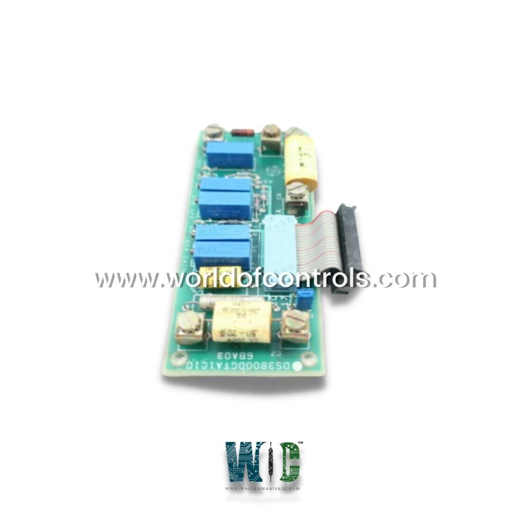
World Of Controls understands the criticality of your requirement and works towards reducing the lead time as much as possible.
DS3800DGTA - Daughterboard Assembly Module is available in stock which ships the same day.
DS3800DGTA - Daughterboard Assembly Module comes in UNUSED as well as REBUILT condition.
To avail our best deals for DS3800DGTA - Daughterboard Assembly Module, contact us and we will get back to you within 24 hours.
SPECIFICATIONS:
Part Number: DS3800DGTA
Manufacturer: General Electric
Series: Mark IV
Product Type: Daughterboard Assembly Module
Number of channels: 12
Input Pulse Rate: 10 Hz to 25 kHz
Input Voltage Range: 24 V DC
Operating Voltage: ±5V, ±15V DC
Operating Temperature Range: 0°C to +60°C
Communication Interface: Backplane bus
Weight: 0.45 kg
Power Consumption: 2–5 Watts
Size: 8.25 cm high x 4.18 cm
Repair: 3-7 days
Availability: In Stock
Country of Origin: United States
FUNCTIONAL DESCRIPTION:
DS3800DGTA is a Daughterboard Assembly Module manufactured and designed by General Electric as part of the Mark IV Series used in GE Speedtronic Control Systems. It is a specialized circuit board designed to enhance the capabilities of the main control system in gas turbine engines. These cards facilitate various functions, such as data acquisition from sensors that monitor critical parameters like temperature, pressure, and vibration, while also performing signal processing to ensure accurate data transmission. It performs signal conditioning, scaling, and interfacing functions for analog and digital I/O channels. The module facilitates high-speed data exchange between the field devices and the core controller via the backplane bus. It includes onboard passive components, edge connectors, and calibration points to support real-time control logic, trip status signaling, and redundancy where applicable.
WOC offers the largest inventory of OEM replacement parts for GE Speedtronic Control Systems. We also provide expert repair services for faulty boards, along with a wide selection of unused and refurbished modules, each backed by a warranty. Our experienced support team is available 24/7 to assist with your OEM and automation requirements. For inquiries regarding pricing, availability, or repair services, please contact us via phone or email.
What should I do if the module is not responding after installation?
First, check that the board is firmly seated in its slot and all edge connectors are properly aligned. Verify that the backplane is supplying the correct voltages (±5V, ±15V). Also, inspect for any bent pins or loose ribbon cables.
What tools can I use for troubleshooting this board?
A digital multimeter (DMM) can be used to check voltage levels at test points. An oscilloscope may help analyze signal integrity. Some systems support loopback tests and built-in diagnostics accessible through the operator interface.
How can I verify if the inputs/outputs are functioning correctly?
Use simulated input signals (loop calibration tools or test signal injectors) and monitor system response via the controller or HMI. Output channels can be verified using field test lamps or diagnostic indicators.