World Of Controls understands the criticality of your requirement and works towards reducing the lead time as much as possible.
DS2020PDMAG4 - Power Distribution Module is available in stock which ships the same day.
DS2020PDMAG4 - Power Distribution Module comes in UNUSED as well as REBUILT condition.
To avail our best deals for DS2020PDMAG4 - Power Distribution Module, contact us and we will get back to you within 24 hours.
SPECIFICATIONS
Part Number: DS2020PDMAG4
Manufacturer: General Electric
Series: Mark V
Number of Input Sources: 125 Volt
Outputs: 2 TMR I/O Racks
Product Type: Power Supply
Availability: In Stock
Country of Origin: USA
FUNCTIONAL DESCRIPTION
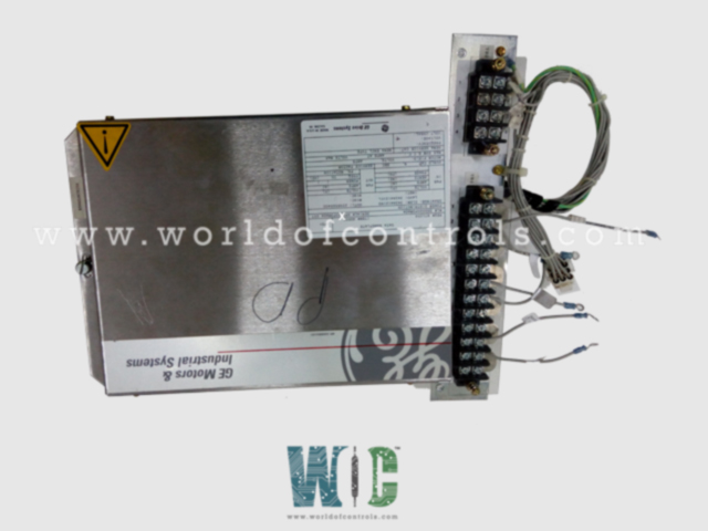
DS2020PDMAG4 is a Power Distribution Module manufactured by General Electric as part of the Mark V Series used in gas turbine control systems. The Mark V system receives 125 V de and 115 V ac (or 230 V ac) from the Power Distribution Module (PDM) for all racks and terminal boards. For systems using remote I/O cabinets, there is a second version of the PDM for the control cabinet.
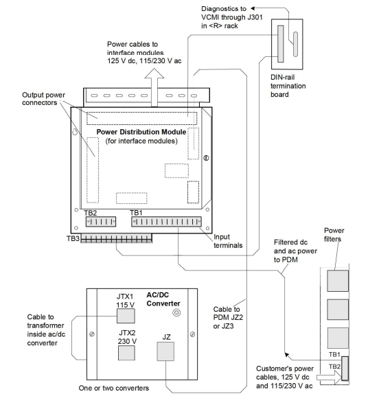
Fig 1: Power Distribution Module, AC to DC Converter & Diagnostic Cabling
INSTALLATION:
The interface cabinet's PDM wire connections, fuse positions, and cabling are depicted in fig.
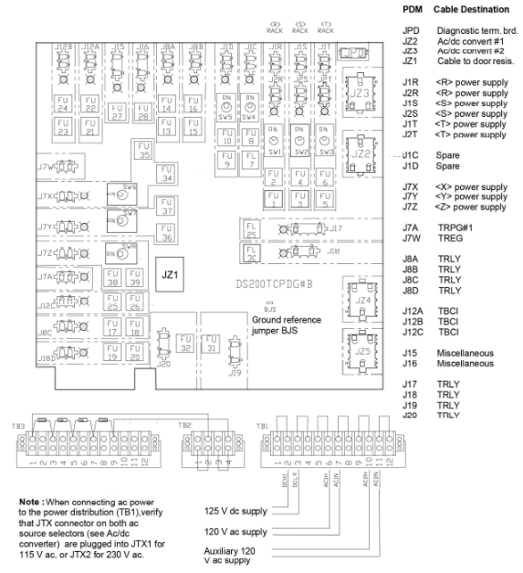
Fig 2: Interface Cabinet PDM Circuit Board
OPERATIONS:
Power filters are used to enter the PDM with the customer's 125 V de and 115/230 V ac power. One or two ac/de converters that produce 125 V de are wired to receive the ac power. When this de voltage is cabled back into the PDM and diode linked to the main depower, a backup power source is created. The VME racks and terminal boards receive this power distribution. The ac/de converters are capable of handling either 230 V or 115 Vac. For 230 V ac operation, the transformer cable must be inserted into either JTX2 or JTXI. The PDM is used to gather diagnostic data, which is then linked to a terminal board installed on a DIN rail. Then, a cable travels through 1301, ending at the VCMI in rack-R. Fused and cabled out to the relay terminal boards are the ac feeds, J17–20.
The interface (I/O) cabinets, protection modules, TRPG, TREG, and TRLY are all connected by cables with fuses on them. The PDM is delivered through a control power filter (CPF), which reduces EMI noise, to ensure a noise-free supply to the boards. According to the next figure, the CPF rack can store two or three Corcom 30 A filter modules. Before being fused and cabled to the TBCI boards, power to the contact inputs first goes via TB2, then through resistors R3 and R4, then through TB2. Operation of contact inputs requires 125 V de-excitation.
CONTROL CABINET PDMA:
The control cabinet requires less power than the interface cabinet. Given that just the control racks and relay output boards need power, the PDM has a similar layout but differing fuse ratings. Corcom power filters are included with the PDM to provide the controllers with additional noise filtering.
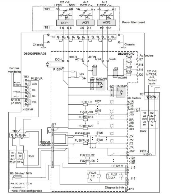
Fig 3: Distribution Module For I/O Cabinet
Ground Fault Detection Sensitivity:
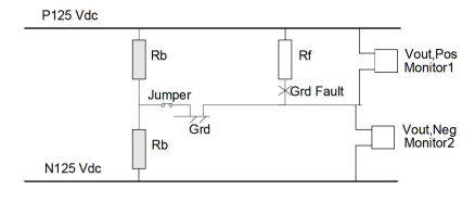
Monitoring the voltage between the floating 125 V de power bus and the ground is the basis for ground fault detection. The bus voltages are generally balanced (in magnitude), meaning that the positive bus voltage and the negative bus voltage are equal. According to the diagram, the bridging resistors, Rb, cause the bus to be in a balanced state. The bus voltages with respect to the ground will be out of balance if there is bus leakage (or a ground fault) from one side.
POWER DISTRIBUTION MODULE:
ELECTRICAL CIRCUIT MODULE:

The bus voltage, the fault resistance, the bus to the ground voltage (Vout), and the bridge resistors all have the following relationships.
Vout = Vhus R/12 (RF+ Rh/2)]
Therefore the threshold sensitivity to ground fault resistance is as follows:
Rf Vour Rb (Vhus-2 Vout)
DIAGNOSTICS:
The 125 V de is lowered to signal level for monitoring by a resistance divider network, as indicated in the following diagram. The battery voltage, two AC sources, and fuses in the feeders to the relay output boards are among the other things examined. This diagnostic data is monitored by the VCMI in the interface cabinet; in the control cabinet, it is cabled to the VDSK board before being sent to the VCMI.
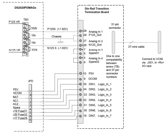
Fig 4: PDMA Diagnostics Monitoring
CONFIGURATION:
Switches: There are several jumpers and switches on the PDM for the I/O cabinets, as shown below. See the circuit diagrams for information on placement and operation.
Jumpers: There are jumpers on TB2 and TBI. On TB3, there are resistors that lower the 125 V dc to 1.82 V de so that the bus may be monitored.
Ground reference Jumper: For ground reference isolation on systems with an external ground reference, jumper BIS is provided. The center of the ground reference bridge is connected to the ground by BJS, and it has two resistances—one on each side—across the 125 V depower.
WOC has the largest stock of GE Speedtronic Mark V Replacement Parts. We can also repair your faulty boards. WORLD OF CONTROLS can also supply unused and rebuilt backed up with a warranty. Our team of experts is available round the clock to support your OEM needs. Our team of experts at WOC is happy to assist you with any of your automation requirements. For pricing and availability on any parts and repairs, kindly get in touch with our team by phone or email.
FREQUENTLY ASKED QUESTIONS
How does a power distribution board work?
Distribution panels function by bringing together circuits from many sites into a single hub.
Are the Products Genuine OEM Units?
These items have been certified by WOC Quality Control to be genuine OEM Units obtained through OEM or independent third-party channels.
How to Check Price and Availability For DS2020PDMAG4?
Please Contact World of Controls FZE for sales at +1 609 385 1231 or Request a Quote.