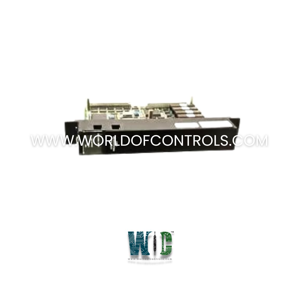
IC697CPU788 - Programmable Logic Controller Module

IC697CPU788 - Programmable Logic Controller Module IC697CPU788 - Programmable Logic Controller Module

World Of Controls understands the criticality of your requirement and works towards reducing the lead time as much as possible.

IC697CPU788 - Programmable Logic Controller Module is available in stock which ships the same day.

IC697CPU788 - Programmable Logic Controller Module comes in UNUSED as well as REBUILT condition.

To avail our best deals for IC697CPU788 - Programmable Logic Controller Module, contact us and we will get back to you within 24 hours.

SPECIFICATIONS

Part No.: IC697CPU788
Manufacturer: General Electric
Product Type: Programmable Logic Controller Module
Module Type Expandable CPU (Triple Redundancy)
Number of Slots: 1 (Single slot)
Current Required: 1.6 Amps
Number of Points: 352 discrete inputs and outputs (any mix)
Serial Ports: One
Supports: IC660/IC661 I/O and IC697 I/O
Availability: In Stock
Series: VersaMax

Functional Description

IC697CPU788 is a Programmable Logic Controller Module developed by GE. It is a 32-bit Programmable Logic Controller (PLC) module developed by GE Automation. It is designed to operate in critical environments, such as those in IC660/661 systems, where reliable control and emergency shutdown capabilities are essential. It supports Triple Modular Redundancy (TMR) when used with C program blocks, ensuring high availability and fault tolerance in mission-critical applications.

Features

  • Processor and Speed: The module is powered by a 16 MHz 32-bit microprocessor that supports fast processing speeds, with the ability to execute Boolean functions every 0.4 microseconds.
  • Modular Redundancy Support: The module is optimized for use in Triple Modular Redundancy (TMR) systems, making it ideal for applications where system reliability and continuous operation are paramount.
  • I/O Support: The module supports a range of smart option modules, including:
    • IC697 LAN and I/O link interface modules
    • Alphanumeric display modules
    • Bus controllers for IC660 and IC661 devices
    • IC697 discrete and analog I/O modules
  • Memory Expansion: To support program and data storage, the module allows the attachment of an expansion memory board with 512 Kbytes of battery-backed CMOS RAM, of which approximately 200 Kbytes is available for user application programs and data.
  • Data Storage: The module stores program data in CMOS RAM supported by a lithium battery, ensuring the persistence of data even in the event of power loss.

Operating Modes and Control

  • Manual Mode: The CPU features a three-position RUN/STOP switch located on the front panel. This switch allows for local control of the system’s operational state, enabling the user to quickly switch between RUN, STOP, and RESET modes during commissioning, maintenance, or troubleshooting.
  • Remote Operation: When connected to a programming computer running compatible software (such as Logicmaster 90 or Proficy Machine Edition), the CPU can be operated remotely via serial, parallel, or Ethernet interfaces (with optional communication hardware).

This flexibility allows for easy configuration and operation either on-site or remotely.

Configuration and Security

  • Software Configuration: Configuration is performed using a computer running MS-DOS (or Windows 95/NT), with serial or parallel connections for programming. Optionally, an Ethernet interface can be used if special hardware is installed.
  • Security: To prevent unauthorized changes, configuration data can be protected by passwords and a physical protection switch. When the switch is in the protected position, program and configuration changes can only be made through a parallel programmer connection (i.e., via the Bus Transmitter module).

Installation Process

  • Power Down the Rack: Always turn off the power to the PLC rack before beginning installation to prevent electrical damage or personal injury.
  • Set Configuration Protect Switch to OFF: This allows the system to accept configuration and logic changes during the initial setup phase.
  • Install the Lithium Battery: Insert the battery pack to enable non-volatile memory backup for logic and data retention in the event of power loss. This battery also supports the CPU’s real-time clock.
  • Attach Memory Expansion Board: If additional memory is required, mount the memory expansion daughterboard (e.g., IC697MEM733 or IC697MEM735) using a Phillips screwdriver to secure the board properly to the CPU module.
  • Install CPU Module into Rack: Align and insert the module into the appropriate CPU slot in the rack. Ensure all connectors are firmly seated and fasteners are tightened.
  • Restore Rack Power: Once everything is securely in place, restore power to the rack. Use the programming software to clear or initialize the memory and begin configuration. Upon powering up, the top LED will blink during diagnostics. Once the diagnostics are complete, the top LED will remain on, signaling that the module is ready for programming.

Memory and Program Storage

It requires an expansion memory board for operation, providing 512 Kbytes of CMOS RAM. About 200 Kbytes of this memory is allocated for the user application program and data, while the remaining space supports system-level operations.

LED Indicators and Status

The status can be monitored via four green LEDs on the front of the module:

  • Top LED: Indicates the operational status (on when ready, blinking during diagnostics).
  • Second and Third LEDs: Indicate specific operational states.
  • Fourth LED: Signals whether the keyswitch is in the OFF position.

The LED indicators help users track system performance, module status, and operational mode.

Expansion Memory Requirements

For full functionality, requires the installation of a CMOS RAM expansion memory board. The expansion memory provides an additional 512 Kbytes of storage, supporting user applications and ensuring robust operation in complex systems. A battery-backed CMOS memory ensures data persistence, even in the event of power interruptions.

Programming and Configuration

Programming is done using a computer connected via parallel (MS-DOS) or serial interface, with configuration software available for Windows 95/NT. The configuration process is streamlined, eliminating the need for jumpers or DIP switches. It also supports Ethernet interfaces when special hardware is in place for more advanced setups.

The WOC team is always available to help you with your Mark I and II requirements. For more information, please contact WOC.

Frequently Asked Questions

What is IC697CPU788?
It is a Programmable Logic Controller Module developed by GE under the VersaMax series.

What do the LED indicators on the PLC mean?
Top LED Indicates operational status (blinks during diagnostics and remains on when ready). Second and Third LEDs Show specific operational states. Fourth LED Signals whether the configuration protection switch is in the OFF position.

What is the role of the CMOS expansion memory board?
The CMOS expansion memory board is required for full operation. It provides an additional 512 Kbytes of CMOS RAM, which supports user applications and ensures data persistence with a battery-backed system.

What programming software is used for the PLC?
Programming and configuration of the PLC are done using programming software compatible with MS-DOS or Windows 95/NT. The connection to the PLC can be made via serial, parallel, or Ethernet (with appropriate hardware).

How is the PLC integrated into a system?
The PLC integrates into a system through its backplane-mounted rack, which allows communication with I/O modules and other devices. It is ideal for applications requiring high reliability and fault tolerance, such as Triple Modular Redundancy (TMR) environments.