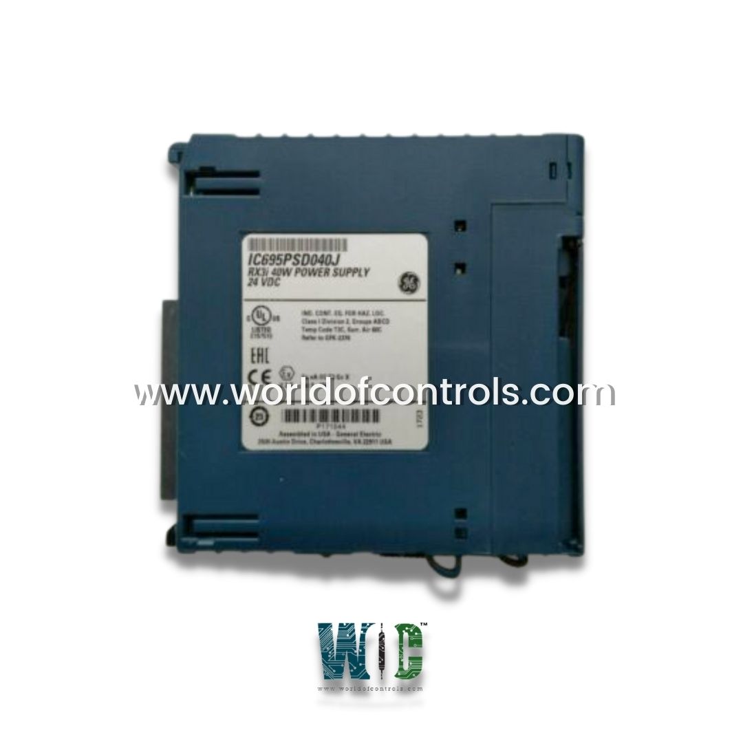
World Of Controls understands the criticality of your requirement and works towards reducing the lead time as much as possible.
IC695PSD040 - 40-Watt DC Power Supply Module is available in stock which ships the same day.
IC695PSD040 - 40-Watt DC Power Supply Module comes in UNUSED as well as REBUILT condition.
To avail our best deals for IC695PSD040 - 40-Watt DC Power Supply Module, contact us and we will get back to you within 24 hours.
SPECIFICATIONS:
Part No: IC695PSD040
Manufacturer: General Electric Fanuc
Product Type: 40-Watt DC Power Supply Module
Product Line: RX3i PacSystem
Compatibility: PACSystems RX3i
Switchover time: Maximum 1 logic scan
Series: PACSystem RX3i
Input voltage range: 18 to 30 VDC
Power Supply: 40 Watts
Communication standards: RS232
Nominal Rated Voltage: 24 VDC
Processor Speed: 1.1G Hertz
Input Voltage Start: 18 to 30 VDC
Voltage Range: 18 to 30 VDC
Protocol Support: Modbus RTU Slave
Backplane: Universal backplane
Weight 0.75 lbs
Size: 8.83 x 3.58 x 4.7 inches
Product Lifecycle: Discontinued By Manufacturer
Availability: In Stock
Country of Origin: USA
FUNCTIONAL DESCRIPTION:
IC695PSD040 is a 40-Watt DC Power Supply Module manufactured and designed by General Electric as part of the Mark II Series used in GE Speedtronic Control Systems. Power Supply is a 40-Watt supply that operates from an input voltage source in the range of 18 VDC to 30 VDC. This power supply provides three outputs:
Power Supply version IC695PSD040 or before may cause equipment damage if inadvertently installed in the same backplane as another RX3i power supply. This DC Power Supply occupies one backplane slot. If the number of modules required exceeds the capacity of the Power Supply, the additional modules must be installed in Expansion or Remote backplanes, or power supplies capable of increased capacity mode operation must be used. The Power Supply indicates when an internal fault occurs so the CPU can detect loss of power or log the appropriate fault code.
LED OF POWER SUPPLY MODULE:
OVERCURRENT PROTECTION:
The 5.1 VDC output is electronically limited to 7 Amps. The 3.3 VDC output is limited to 10 Amps. If an overload (including short circuits) occurs, it is sensed internally and the Power Supply shuts down. The Power Supply continually tries to restart until the overload condition is removed. An internal fuseable link in the input line is provided as a backup. The Power Supply usually shuts down before the fuse blows. The fuse also protects against internal supply faults. The CPU Fault Table shows a fault if any Overtemperature, Overload, or P/S Fault occurs. There is no additional indication if the Power Supply fuse blows.
INPUT OVERVOLTAGE PROTECTION:
The bottom terminal is normally connected to frame ground with a user-installed jumper, as shown at lower right. If overvoltage protection is not required or is supplied upstream, no jumper is required. To Hi-pot test this supply, overvoltage protection must be disabled during the test by removing the jumper. Re-enable overvoltage protection after testing by reinstalling the jumper. Each terminal accepts one AWG 14 to AWG 22 wire. The end of each wire should be stripped at least 3/8-inch (9mm). The terminal can accept a wire that is stripped up to 11 mm (.433 in) while providing full seating of the insulator. The wire must be fully inserted as shown at left, so that the insulation meets the insulation stop position inside the terminal. Tightening the terminal screw pivots the clamp firmly against the stripped end of the wire, holding it in place. If the wire is not fully inserted as shown at right, tightening the terminal screw may push the wire upward so that it is not connected.
WOC maintains the largest inventory of OEM replacement parts for GE Speedtronic Turbine Control Systems, ensuring that your operations remain uninterrupted. In addition to supplying new and unused parts, we also offer expertly rebuilt and refurbished boards, each backed by a comprehensive warranty for your peace of mind. Our highly trained team of automation specialists is available 24/7 to provide technical support, assist with troubleshooting, and help you identify the exact parts or solutions you need for your turbine control systems. Whether you require emergency repairs, routine maintenance, or assistance with system upgrades, WOC is committed to delivering reliable, high-quality service tailored to your operational requirements. For pricing, availability, or consultation on parts and repair services, please contact our team directly by phone or email, and we will ensure prompt and professional support.
What is the input voltage range for this power supply?
The module operates from 18 to 30 VDC, with a nominal voltage of 24 VDC. It delivers stable output within this range, making it suitable for PACSystem RX3i applications. Voltages outside this range may trigger a fault or shutdown.
What outputs does the power supply provide?
It provides +24 VDC for external relay circuits and +3.3 VDC for internal module operation. These outputs ensure reliable power delivery to connected modules and system stability.
How much power can the supply provide?
The module delivers 40 Watts of DC power, adequate for standard RX3i modules and relay circuits. Exceeding this capacity will trigger overcurrent protection.
Can multiple modules be installed in the same backplane?
Earlier versions must not be installed alongside another power supply in the same backplane to prevent damage. For additional modules, use expansion or remote backplanes or higher-capacity supplies.