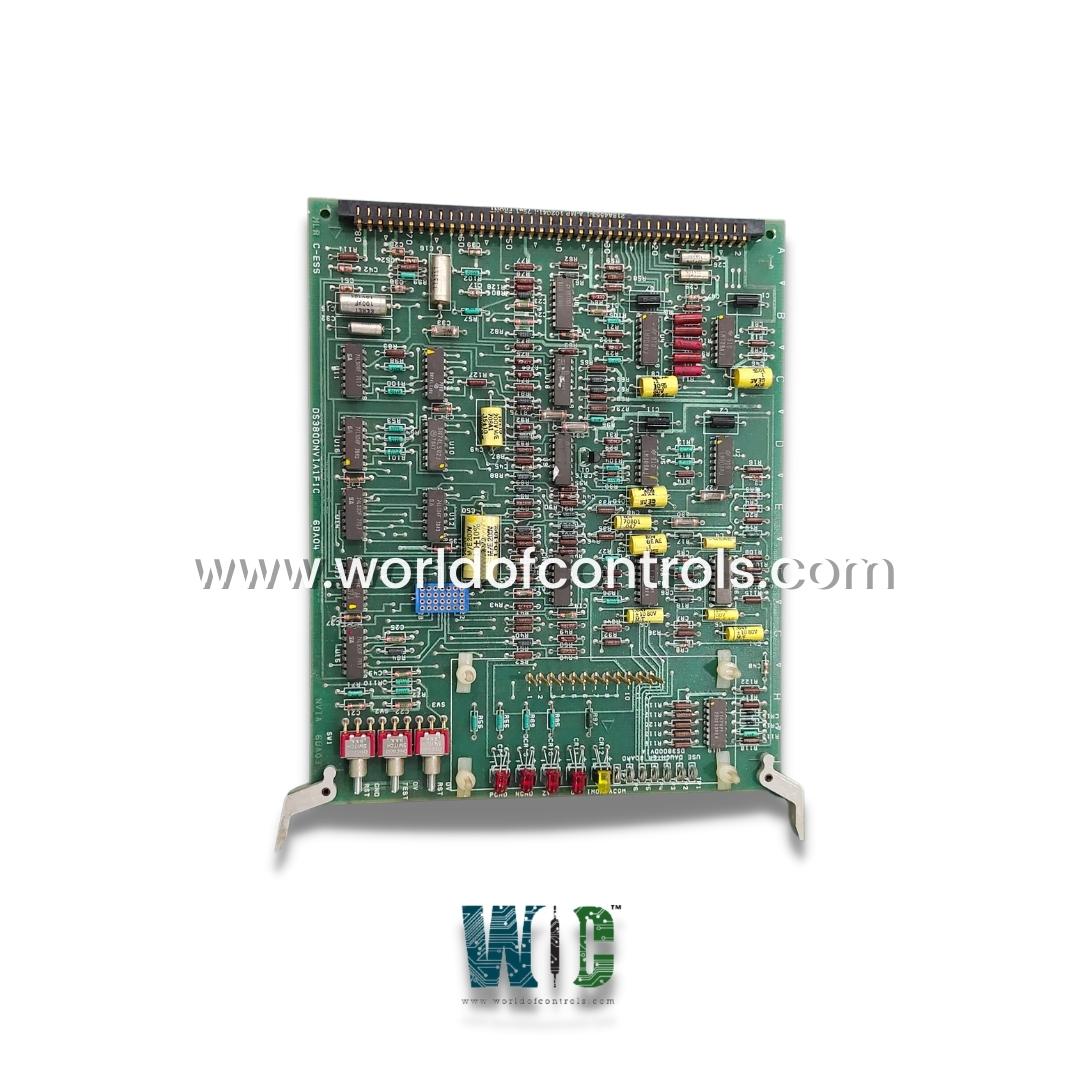
World Of Controls understands the criticality of your requirement and works towards reducing the lead time as much as possible.
DS3800NVIA1F1C - Voltage Isolator Board is available in stock which ships the same day.
DS3800NVIA1F1C - Voltage Isolator Board comes in UNUSED as well as REBUILT condition.
To avail our best deals for DS3800NVIA1F1C - Voltage Isolator Board, contact us and we will get back to you within 24 hours.
SPECIFICATIONS:
Part Number: DS3800NVIA1F1C
Manufacturer: General Electric
Series: Mark IV
Product Type: Voltage Isolator Board
Input Signal Voltage Range: 0 to 10 V DC
Isolation Voltage: ≥ 1500 V RMS
Signal Linearity: ±0.1%
Input Impedance: > 100 k Ohms
Frequency Response: DC to 1 kHz
Board Size: 15.7 cm High x 18.5 cm
Operating Temperature Range: -20 °C to +70 °C
Power Supply: +5 V DC
Connector Type: 96-pin
Repair: 3-7 Days
Weight: 1.00 lbs
Country of Origin: USA
Availability: In Stock
FUNCTIONAL DESCRIPTION:
DS3800NVIA1F1C is a Voltage Isolator Board manufactured and designed by General Electric as part of the Mark IV Series used in GE Speedtronic Gas turbine control systems. The Voltage Isolator Board provides galvanic isolation between analog voltage input/output signals and the main control system to prevent ground loops and electrical noise interference. It isolates signal grounds to protect the turbine control electronics from transient voltages, surges, and common-mode noise. Internally, the board uses precision isolation amplifiers and opto-isolators to maintain signal integrity while breaking direct electrical connections. This ensures accurate voltage signal transmission, critical for real-time turbine monitoring and control.
INSTALLATION:
The board is designed for plug-in installation into the GE Mark IV Speedtronic control cabinet backplane. Proper mechanical seating and connection to the 96-pin edge connector ensure signal and power interface. Installation must comply with GE's hardware handling procedures, including ESD precautions and proper grounding of the control cabinet chassis to maintain isolation performance. Wiring to external sensors and I/O terminals must follow GE wiring diagrams, ensuring correct polarity and shielding to minimize interference. After installation, perform continuity and isolation resistance tests using a megohmmeter to verify correct installation and isolation integrity.
OPERATION:
The board accepts analog voltage inputs from sensors or other control devices, isolates these signals, and outputs a conditioned voltage signal to the Speedtronic Mark IV control processor. It maintains linearity and low signal distortion within specified bandwidth limits. The isolation barrier withstands high common-mode voltages (typically in the kilovolt range) to ensure safe operation in electrically noisy environments such as power plants. The board supports input voltage ranges commonly used in turbine control systems (e.g., 0–10 VDC) and provides a stable output with minimal offset voltage and low temperature drift.
COMPATIBILITY:
This Voltage Isolator Board is fully compatible with GE Speedtronic Mark IV hardware and firmware versions supporting analog signal isolation modules. It interfaces with analog input/output cards and turbine sensor arrays in typical gas and steam turbine control configurations. The board meets GE specifications for environmental ratings, including temperature, humidity, and vibration, as required in industrial turbine control environments. Replacement or retrofit must be done with genuine or GE-certified parts to ensure compliance with system safety and performance standards.
WOC offers the largest inventory of replacement parts for the GE Speedtronic Mark IV control system, including new, surplus, and expertly refurbished boards, all backed by a reliable warranty. Every component undergoes thorough testing to ensure optimal performance and compatibility. In addition to part supply, we provide specialized repair services for faulty boards, restoring them to OEM standards using advanced diagnostics and repair procedures.
Our team of experienced engineers is available 24/7 to support your OEM and automation needs, including part identification, technical guidance, and real-time troubleshooting. Whether you're looking for immediate part availability, cost-effective repairs, or expert advice, WOC is your trusted partner. For inquiries related to pricing, stock status, or repair services, contact us via phone, email, or our website. We're here to help keep your systems running efficiently.
What are the symptoms of a failing Voltage Isolator Board?
A failing board typically manifests through unstable or absent analog signal readings in the turbine control interface. Operators may notice fluctuating voltage inputs or outputs, alarms generated by the analog processing modules, or turbine misbehavior due to erroneous signal conditioning. Other signs include loss of communication with sensor data points and intermittent control errors tied to voltage measurement. In some cases, the board may completely fail to transmit voltage signals, resulting in safety system shutdowns or process faults.
How can I verify if the board is isolating properly?
To test the isolation capability of the board, a megohmmeter (insulation resistance tester) should be used to measure resistance between the board’s input and output terminals. A healthy board typically shows insulation resistance greater than 1 G Ohms when tested at 500 VDC. Any significant reduction in this value indicates potential breakdown of the isolation barrier, such as internal leakage or dielectric failure within the isolating amplifiers. This test is especially important if ground loops or signal cross-talk are suspected in the system.
The input voltage is correct, but the output is zero. What could be wrong?
If the input signal to the board is within the expected voltage range, but there is no output, several failure modes are possible. One common cause is the failure of the internal isolation amplifier, which could be due to electrical overstress or component degradation. It's also important to confirm that the board is receiving its required power from the Mark IV backplane, typically +5 VDC or ±15 VDC, depending on the design. Poor contact with the edge connector or dirty pins can also interrupt signal transmission.