SPECIFICATIONS
Part No.: DS2020CMA1206C8DDD 88
Manufacturer: General Electric
Country of Manufacture: United States of America (USA)
Temperature Operating: -30 to 65oC
Product Type: PLC Module Rack Chassis
Availability: In Stock
Series: LCI
Functional Description
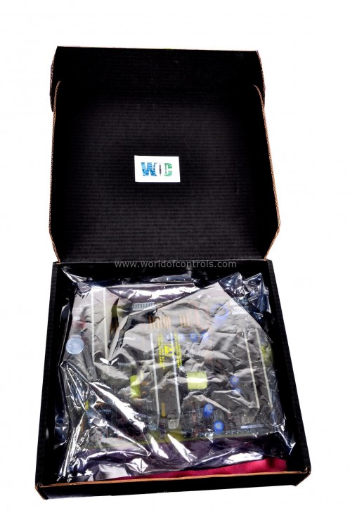
DS2020CMA1206C8DDD 88 is a PLC Module Rack Chassis developed by GE. It is a part of LCI (Load Commutated Inverter) series. It is designed for the efficient housing and operation of programmable logic controller (PLC) modules. The chassis supports multiple PLC modules, enabling flexible configurations and easy expansion based on system requirements.
Features
- Built with industrial-grade materials, it ensures durability and resistance to environmental factors such as dust, heat, and vibration.
- Integrated power distribution ensures consistent and stable power supply to all connected modules.
- Designed to integrate seamlessly with GE's range of PLC modules, offering high compatibility and operational reliability.
- Equipped with efficient cooling features to prevent overheating during continuous operations.
- Provides centralized housing for PLC modules in automated production lines.
- Supports control systems in power generation and distribution plants.
- Helps manage HVAC, lighting, and security systems effectively.
Installation and Replacement Procedure
- Preparation: Turn off the power supply to the chassis. Ensure the workspace is free from dust and other contaminants.
- Module Removal: Gently disconnect any cables connected to the module. Unlock the module from the chassis and slide it out carefully.
- Chassis Installation: Position the chassis in the desired location, ensuring it is secured and properly grounded. Mount the chassis using appropriate fasteners.
- Module Installation: Insert the module into the appropriate slot and secure it in place. Reconnect cables and verify the connections are firm and correctly labeled.
- Power-Up and Testing: Power on the chassis and test the system to ensure proper functionality.
Coolant Circulating System
- The coolant circulating system is designed for continuous and efficient operation, featuring isolation valves that enable online pump replacement without draining the entire system. This functionality minimizes downtime during maintenance and ensures seamless performance in critical applications.
- To maintain reliable coolant circulation, the system employs redundant pumps. Automatic transfer to a backup pump is triggered when the differential pressure drops to 7 psi, supported by a differential pressure switch and interlocking pump motor starters. Under normal conditions, the system operates within a stable pressure range of 15 to 40 psi.
- The system is self-venting, eliminating the need for manual air purging during regular operations. For additional flexibility, a manual vent is located on the outlet side of the power conversion bridge, allowing for precise control during maintenance or troubleshooting.
- The storage reservoir operates at atmospheric pressure and ensures a steady inlet flow to the circulating pumps. Made from low-density polyethylene, it features a screw cap to prevent contamination and evaporation. The reservoir includes a vent for atmospheric pressure balancing and must remain covered to avoid unnecessary exposure.
- The system supports both liquid-to-air and liquid-to-liquid heat exchangers. The liquid-to-air option includes redundant cooling blowers with automatic transfer capabilities, while the liquid-to-liquid option, designed for remote installation, provides an alternative that eliminates the need for blowers. Both configurations offer flexibility to meet diverse cooling requirements.
The WOC team is always available to help you with your LCI requirements. For more information, please contact WOC.
Frequently Asked Questions
What is DS200VPBLG1ADD?
It is a VME Backplane Board developed by GE under the LCI series.
What is the primary function of the board?
The board acts as a communication and power distribution hub for the components installed in the J2 and J3 sections of the card cage. It ensures separate analog and digital power planes for optimal system performance.
What connections are established in the J3 section?
Current Transformers (CTs) and associated burden resistors, Voltage Scaling Feedback Board connections, It also facilitate power connections and various grounding schemes.
What precautions should I take while handling the board?
Power off the equipment before starting. Handle connectors and cables gently to avoid damage. Ensure the board is kept level during removal and installation. Prevent hardware from dropping onto the board or into the equipment.
