SPECIFICATIONS
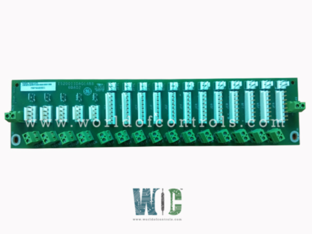
Part No.: IS200IIDAG1ABB
Manufacturer: General Electric
Country of Manufacture: United States of America (USA)
Temperature: -30 to + 65oC
PCB Coating: Normal Coating
Product Type: Direct Current Innovation Card
Availability: In Stock
Series: EX2100
Functional Description
IS200IIDAG1ABB is a Direct Current Innovation Card developed by GE. It is a part of EX2100 excitation system. Designed to offer a robust framework for handling critical control and protection parameters, the board redefines reliability and precision in the realm of DC innovation. With its Ethernet communication capabilities, PC-based Operator Interface on a Windows platform, and a Central Control Module featuring triple redundant backups, this card ensures operational integrity in various applications.
Robust Framework
- Offers a robust framework tailored to manage critical control and protection parameters effectively.
- It ensures operational integrity across various applications, guaranteeing optimal performance and reliability.
Communication Capabilities
- Equipped with Ethernet communication capabilities, facilitating seamless data exchange and integration with other systems.
- Supports PC-based Operator Interface operating on a Windows platform, enabling intuitive control and monitoring functionalities.
Central Control Module
- Features a Central Control Module with triple redundant backups, ensuring continuity of critical functions even in the event of component failures.
- This redundancy enhances system reliability and minimizes the risk of downtime.
Component Composition
- Consists of Ethernet communications and a PC-based Operator Interface running on a Windows platform.
- Incorporates a Central Control Module with triple redundant backups for critical control and protection parameters.
Component Structure
- Conduction sensors are strategically located at the front corners of the card, facilitating efficient heat dissipation and temperature management.
- Factory-drilled holes at the back corners enable straightforward installation and mounting in various configurations.
- Components are clearly marked with industry-standard reference designators and specific codes for easy identification and troubleshooting.
Safety Precautions and Handling
- Rigorous safety precautions are essential due to the presence of potentially hazardous surface voltages. Grounding straps are recommended throughout the installation process to minimize the risk of electrical shocks.
- Prior to installation, it's imperative to power down the greater drive assembly to mitigate potential risks and ensure safe handling.
Product Information and Revisions
- Specific revision details include Functional Revision 1 rated as A, Functional Revision 2 rated as B, and Artwork Revision rated as B.
- These revision ratings denote the functionality and artwork improvements incorporated into subsequent iterations of the card.
Software Features
- Emulation of Traditional Analog Controls: The software emulates traditional analog controls, providing familiarity and ease of use for operators accustomed to conventional control interfaces. This emulation ensures a smooth transition to digital control systems while retaining the intuitive operation of analog counterparts.
- Open Architecture System: The exciter application software adopts an open architecture system, facilitating flexibility and customization to suit specific application requirements. A library of existing software blocks is available, configured from a toolbox, allowing for the creation of tailored control strategies.
- Modular Software Blocks: The software comprises modular blocks, each designed to perform specific functions
- Logic Gates: Enable logical operations such as AND, OR, and NOT.
- Proportional Integral (P.I.) Regulators: Facilitate precise control by adjusting output based on error and integral of error.
- Function Generators: Generate customized waveforms or signals for various control purposes.
- Signal Level Detectors: Monitor signal levels and trigger actions based on predefined thresholds.
- Control Modes: The control system offers two primary modes of operation.
- Generator Voltage Regulation (Auto Regulation): Automatically adjusts excitation to maintain generator voltage within specified limits.
- Direct Control (Voltage or Current): Provides direct manual control over excitation voltage or current, depending on the application requirements.
- Integrated Protection Functions:
- Over and Under-Excitation Limiting: Prevents excitation levels from exceeding safe operating limits, protecting the generator from damage.
- Power System Stabilization: Helps maintain system stability by adjusting excitation in response to dynamic load changes.
- V/Hz Limiting: Ensures the generator operates within safe voltage-to-frequency ratios, safeguarding against overloading and instability.
The WOC team is always available to help you with your EX2100 requirements. For more information, please contact WOC.
Frequently Asked Questions
What is IS200IIDAG1ABB?
It is a Direct Current Innovation Card developed by GE under the EX2100 series.
What communication systems are supported by the exciter architecture?
The exciter architecture supports Ethernet LAN (Unit Data Highway) communication, allowing seamless integration with various GE equipment such as the Control System Toolbox (toolbox), turbine control, LCI Static Starter, and HMI (operator interface).
What's the role of the PPT in the potential source system?
In the potential source system, the secondary of the Potential Power Transformer (PPT) connects to a 3-phase full-wave inverting thyristor bridge. This bridge supplies both positive and negative forcing voltage to enhance system performance. Negative forcing specifically ensures swift responses during load rejection and de-excitation scenarios.
