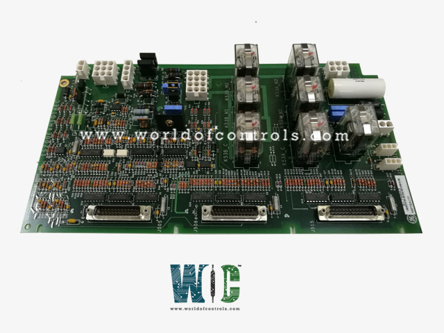
SPECIFICATIONS
Part No.: IS200EXHSG1AEB
Manufacturer: General Electric
Country of Manufacture: United States of America (USA)
Size: 33.02 cm high x 10.16 cm wide
Product Type: Exciter Regulator Exciter High-Speed Relay Driver Board
Availability: In Stock
Series: EX2100
Functional Description
IS200EXHSG1AEB is an exciter regulator Exciter High-Speed Relay Driver Board developed by GE. It is a part of EX2100 excitation system. Exciter High-Speed Relay Driver (EXHS) board plays a critical role within the EX2100 Excitation Control system, primarily providing essential drivers for the management of DC contactors (41) and pilot relays responsible for de-excitation and field flashing functionalities. It is a crucial component in the EX2100 Excitation Control system, overseeing relay operations, conditioning various status signals, and enabling seamless communication between different boards for efficient excitation system management and control.
Features
- Functionality and Relay Control: This board serves as the control hub for various relays, facilitating the operation of the dc contactors (41) and pilot relays associated with de-excitation and field flashing processes within the excitation system.
- Connection and Interface: The boards are connected via cabling to either three Exciter Main Input/Output Boards (EMIO) in redundant control setups or one EMIO board in simplex control configurations. These connections occur through the Exciter Backplane Board (EBKP), ensuring seamless integration and communication between the EXHS board and the EMIO setup.
- Relay Configuration and Monitoring: On the board, pilot relays for flashing relays 53A and 53B, as well as the pilot relays for the de-excitation relay KDEP, are located. Additionally, the board conditions de-excitation status signals received from the Exciter De-Excitation Board (EDEX) and crowbar status signals from the EXDE De-Excitation Control Board. These signals are then transmitted to the EMIO, contributing to system monitoring and control.
- Contact Inputs and Monitoring: Three contact inputs from 41, 53A, and 53B are powered by a 70 V DC source on the EXHS board. These inputs serve as feedback mechanisms that are closely monitored. Power for these contacts is wired in from the exciter power supply, ensuring proper functionality. The resulting status signals from these inputs are carefully monitored and relayed to the EMIO for comprehensive system monitoring and control purposes.
Pilot Relays
- Simplex Control: In simplex control configurations, the EXHSG2 and EXHSG4 modules are responsible for controlling two flashing relays. These pilot relays receive power from a 24 V dc source provided by the M1 controller. Each flashing relay is driven by one pilot relay utilizing two series contacts for operation.
- Redundant Control: For redundant control setups, including EXHSG1, EXHSG3, and inputs from controllers M1, M2, and C, three relays are controlled in a 2-out-of-3 voting circuit. The relay coils in this configuration are powered by the 24 V dc supply from both M1 and M2 controllers.
- Additional Functionality: Each EXHS module includes two 41 dc contactor drivers, which are controlled by a driver on the EMIO. Activation of these drivers is contingent upon receiving a command from the Field Programmable Gate Array (FPGA) and the closure of the 86G contact. Either the FPGA or the 86G contact can trigger the de-energization of the driver, ensuring safe and reliable operation.
Application Data
- K41 (M1, M2, C) serve as the drivers for the close function contactors, while K53A and K53B are designated as the flashing pilot relays within the excitation system. Additionally, KDEP functions as the single de-excitation pilot relay, playing a pivotal role in the de-excitation process.
- Three 25-pin connectors J505, J508, and J515 are designated for cables connecting to the EMIO boards, specifically to M1, M2, and C respectively. These connectors carry similar signals and share comparable wiring configurations. However, it's important to note that J515, the connector for the C board, does not handle de-excitation and crowbar signals.
- Each connector (J505, J508, and J515) maintains a specific connection to the respective EMIO boards. J505 links to board M1, J508 connects to board M2, and J515 links to board C. These connections allow for signal transmission and reception, enabling communication between the EXHS board and the boards.
- Two plugs, J12M1 and J12M2, facilitate the intake of 70 V DC from the power supplies of boards M1 and M2 respectively. This power supply serves the purpose of auxiliary contact wetting, ensuring optimal functionality and reliability of the contacts associated with the board's operations.
- The application data outlines the critical relay drivers, pilot relays, connector details for EMIO board connections, and the provision of power supply for auxiliary contact wetting. This information is crucial for understanding the functionalities and interconnections essential for the effective operation of the EXHS board within the EX2100 Excitation Control system.
The WOC team is always available to help you with your EX2100 requirements. For more information, please contact WOC.
Frequently Asked Questions
What is IS200EXHSG1AEB?
It is an Exciter Regulator Exciter High-Speed Relay Driver Board developed by GE under the EX2100 series.
What pilot relays are situated on the board, and what functions do they serve?
The board hosts pilot relays for flashing relays 53A and 53B, along with pilot relays for managing the de-excitation relay KDEP. These relays are pivotal in controlling flashing operations and de-excitation functions within the excitation system.
How are signals from the EDEX and De-Excitation Control Board processed?
The EXHS board conditions de-excitation status signals from the EDEX and crowbar status signals from the De-Excitation Control Board. Once conditioned, these signals are relayed to the EMIO boards for system monitoring and control.
What powers and monitors the contact inputs on the board?
The contact inputs from 41, 53A, and 53B are powered by a 70 V DC source. Feedback from these inputs is closely monitored. Power for these contacts is wired in from the exciter power supply. The resulting status signals from these inputs are sent to the EMIO boards for monitoring and control.
