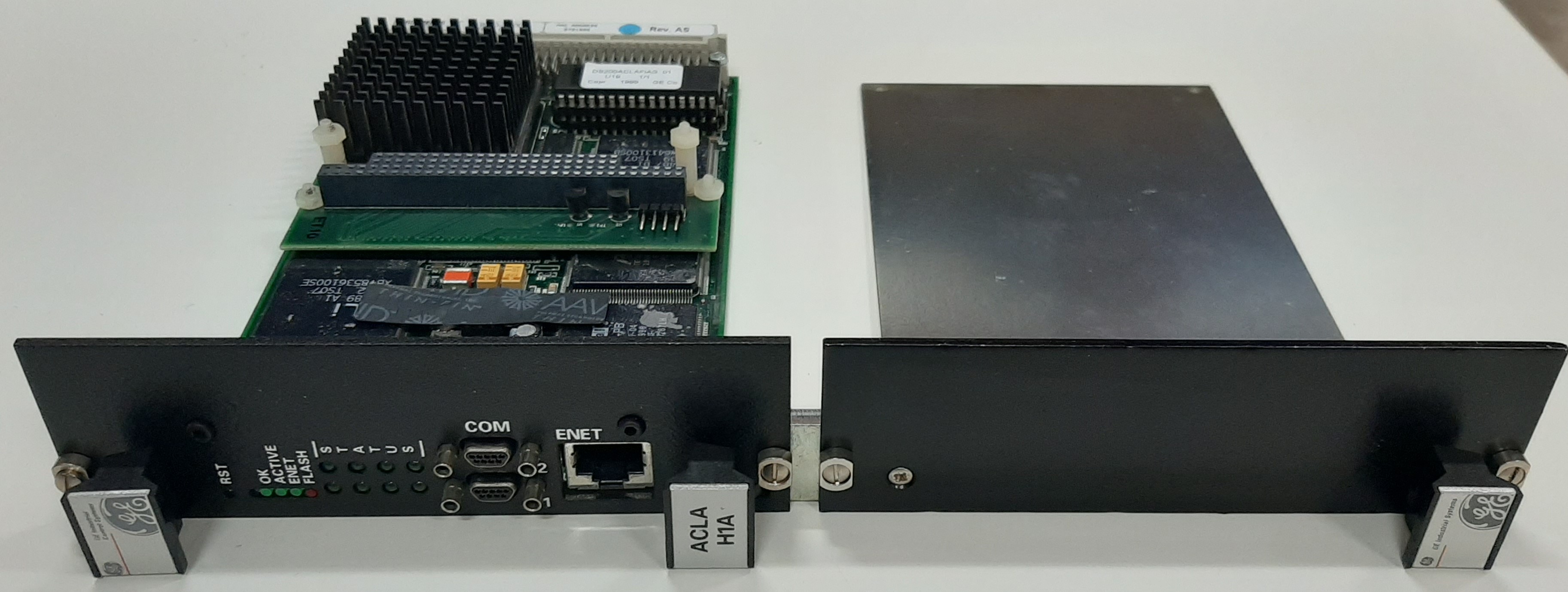
World Of Controls understands the criticality of your requirement and works towards reducing the lead time as much as possible.
IS215ACLAH1A - Application Control Layer Module is available in stock which ships the same day.
IS215ACLAH1A - Application Control Layer Module comes in UNUSED as well as REBUILT condition.
To avail our best deals for IS215ACLAH1A - Application Control Layer Module, contact us and we will get back to you within 24 hours.
SPECIFICATIONS:
Part Number: IS215ACLAH1A
Manufacturer: General Electric
Series: EX2100
Product Type: Application Control Layer Module
Technology: Surface Mount
Operating System: QNX Neutrino
Programming: 16-bit signed integer
Power Requirements: +5 V dc
Memory: 256 MB
Common Mode Voltage Range: ±5 V
Dimensions: 11.00 x 9.00 x 3.00
Operating temperature: 0 to 60 °C
Primary Ethernet Interface: 10BaseT/100BaseTX
No.of Analog Voltage Inputs: 6
Repair: 3-7 Day
Availability: In Stock
Country of Origin: United States
Manual: GEI-100434A
FUNCTIONAL DESCRIPTION:
IS215ACLAH1A is an Application Control Layer Module manufactured and designed by General Electric as part of the EX2100 Series used in GE Excitation Control Systems. The IS215ACL_ Application Control Layer Module (ACL) is a microprocessor-based master controller that performs multiple duties over communication networks such as EthernetTM and ISBus. The ACL mounts in a standard Innovation Seriesô drive or EX2100 exciter board rack and occupies two half-slots. The ACL and board rack are located in the control cabinet. In drive applications, the ACLís P1 connector (4-row 128-pin) plugs into the Control Assembly Backplane Board (CABP). In the EX2100 exciter, the ACL mounts in the Exciter Backplane (EBKP). The ACL can be ordered in two different I/O configurations as follows:
HARDWARE FEATURES:
SOFTWARE FEATURES:
Basic Input/Output System (BIOS) identifies and initializes the hardware. During initialization, the BIOS directs all output display information to the COM1 serial port. The BIOS also supports serial loading of the operating system (compatible with the present GE loader) during the initial boot sequence through the COM1 port.
WOC has the largest stock of GE Excitation Control System Replacement Parts. We can also supply unused and rebuilt backed-up with a warranty. Our team of experts is available round the clock to support your OEM needs. Our team of experts at WOC is happy to assist you with any of your automation requirements. For pricing and availability on any parts and repairs, kindly get in touch with our team by phone or email.
What is the Application Control Layer?
The Application Control Layer is a component of a software system that manages and enforces rules and policies related to application behavior and access.
What does the Application Control Layer module do?
This module regulates which applications can run, how they interact, and what resources they can access within a system or network.
Why is the Application Control Layer important?
It enhances security by preventing unauthorized applications from executing or accessing sensitive data, thereby reducing the risk of malware and data breaches.