World Of Controls understands the criticality of your requirement and works towards reducing the lead time as much as possible.
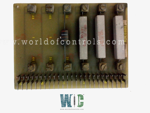
IC3600SCBE1 - Component Assembly Board is available in stock which ships the same day.
IC3600SCBE1 - Component Assembly Board comes in UNUSED as well as REBUILT condition.
To avail our best deals for IC3600SCBE1 - Component Assembly Board, contact us and we will get back to you within 24 hours.
SPECIFICATIONS:
Part No: IC3600SCBE1
Manufacturer: General Electric
Product Type: Component Assembly Board
Series: Mark II
Operating temperature: -30 to 55 ºC
Power Supply Voltage: 24 V dc
Board Size: 2.5 cm high x 8.5 cm
Weight: 0.48 kg
Availability: In Stock
Country of Origin: USA
FUNCTIONAL DESCRIPTION:
IC3600SCBE1 is a Component Assembly Board manufactured and designed by General Electric as part of the Mark II Series used in GE Speedtronic Control Systems. A Component Assembly Board, often referred to as a PCB (Printed Circuit Board), is a fundamental component in many electronic devices. It provides a platform for various electronic components to be connected and organized in a systematic way. The board serves as a backbone for the electrical connections and helps ensure the proper functioning of the device. Here are some key points to understand about a Component Assembly Board:
Substrate: The board is typically made from a non-conductive material, such as fiberglass or composite, and is coated with a layer of conductive copper. This copper layer is etched into pathways and pads to create the electrical connections.
Components: Electronic components, such as resistors, capacitors, integrated circuits, and connectors, are soldered onto the PCB. These components perform various functions and are interconnected to carry out the desired operations of the electronic device.
Traces: The copper pathways, often referred to as traces, act as conductive paths for electrical signals to travel between the components. Traces are carefully designed to ensure the right connections and to minimize interference or crosstalk.
Soldering: Soldering is the process of attaching components to the board using solder, a low-melting-point alloy. Solder joints provide both electrical connections and mechanical support.
Through-Hole vs. Surface Mount: There are two primary methods for attaching components to a PCB: through-hole and surface mount. Through-hole components have leads that go through holes in the board, while surface-mount components are soldered directly to the surface of the PCB. The choice between these methods depends on the specific design requirements.
Design Software: PCB design is typically done using specialized software that allows engineers to create the layout of the board, define component placements, and design the electrical connections. Common software tools for PCB design include Eagle, KiCad, and Altium Designer.
Functionality: The component assembly board plays a crucial role in determining the functionality of electronic devices, as it dictates how components are connected and how signals are routed. It acts as a bridge between hardware components, ensuring they work together as intended.
Testing: Once a PCB is assembled, it undergoes testing to verify that all components are functioning correctly, and there are no defects in the soldering or connections. This is essential to ensure the reliability of the final product.
Variations: PCBs come in various sizes and shapes, depending on the device's requirements. Some PCBs are single-sided, while others are double-sided or even multi-layered for more complex electronics.
WOC has the largest stock of GE Speedtronic Control System Replacement Parts. We can also repair your faulty boards. WORLD OF CONTROLS can also supply unused and rebuilt backed-up with a warranty. Our team of experts is available round the clock to support your OEM needs. Our team of experts at WOC is happy to assist you with any of your automation requirements. For pricing and availability on any parts and repairs, kindly get in touch with our team by phone or email.
How are PCBs tested for quality and functionality?
After assembly, PCBs undergo testing to verify that components are functioning correctly, there are no soldering defects, and electrical connections are sound. Testing methods include visual inspection, continuity testing, and functional testing.
What industries use PCBs?
PCBs are used in a wide range of industries, including consumer electronics (smartphones, laptops), automotive (ECUs, infotainment systems), aerospace, medical devices, and industrial automation.
Can PCBs be repaired if they have issues?
PCBs can be repaired, but the extent of repair depends on the nature of the problem. Minor issues like solder joint reflow can be fixed, but more extensive damage may require component replacement or even the replacement of the entire PCB.