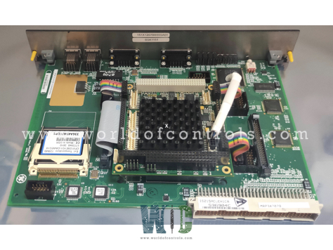
World Of Controls understands the criticality of your requirement and works towards reducing the lead time as much as possible.
IS200ACLEH1C - EX2100 / Mark VI Application Control Layer Module is available in stock which ships the same day.
IS200ACLEH1C - EX2100 / Mark VI Application Control Layer Module comes in UNUSED as well as REBUILT condition.
To avail our best deals for IS200ACLEH1C - EX2100 / Mark VI Application Control Layer Module, contact us and we will get back to you within 24 hours.
TECHNICAL SPECIFICATIONS
Part Number: IS200ACLEH1C
Manufacturer: General Electric (GE)
Control System Series: Speedtronic Mark VI / EX2100 Excitation Series
Functional Acronym: ACLE
Product Type: Application Control Layer Module
Microprocessor Performance: 100 MHz Core Processor
Base Memory Capacity: 8 MB Dynamic RAM (DRAM) & 4 MB Flash Memory BIOS
Secondary Storage Configuration: IDE to SATA Converter carrying a 128 MB Memory Card
Chassis Slot Allocation: Takes up 2 Half-Slots (Wide Front Faceplate Architecture)
Backplane Interface: 4-Row, 128-pin VMEbus P1 Connector Assembly
Integrated Communication Ports: Dual Serial (COM1/COM2), Ethernet (ENET), and Dedicated ISBus Ports
Repair Time: 3-5 Days
Availability: In Stock
Weight: 1.40 kg (3.09 lbs)
Country of Origin: United States
The IS200ACLEH1C is a microprocessor-based Application Control Layer Module (ACLE) designed and manufactured for GE Speedtronic Mark VI turbine control setups and EX2100 Excitation systems. The IS215ACL Application Control Layer (ACL) Module is a microprocessor-based master controller designed to manage multiple functions across communication networks, including Ethernet and ISBus. Installed in a standard Innovation Series drive or EX2100 exciter board rack, the ACL occupies two half-slots and is located within the control cabinet. In drive applications, the module connects to the Control Assembly Backplane Board (CABP) through its P1 128-pin, four-row connector, while in EX2100 exciter systems, it mounts directly on the Exciter Backplane (EBKP). The ACL is available in two I/O configurations, which feature one 10BaseT Ethernet port and two serial communication ports (COM1 and COM2) for EX2100 applications, which include one 10BaseT Ethernet port, two serial communication ports (COM1 and COM2), and two ISBus communication ports for enhanced connectivity. These items must be ordered separately from the ACL and include the following:
HARDWARE FEATURES OF APPLICATION CONTROL LAYER MODULE:
CPU incorporates 16 K byte of internal L1 cache. It is a 486-type processor operating at 100 MHz. The PCI controller manages all memory, I/O, and configuration transfers to and from the PCI bus. Memory and I/O transfers are normal reads/writes from the CPU. Configuration reads/writes must be accessed as 32-bit transfers by writing the configuration address to an I/O port, and then accessing another I/O port to read/write the configuration register. 128 KB Level 2 (L2) Cache is controlled by the PCI controller. The L2 cache is preset to produce 152 Ns cache line fills between the L2 cache and the L1 cache. BIOS is a 1 MB (128 KB x 8) 5 V flash memory device and mounts in a socket on the ACL. See Table 4, Basic BIOS Settings, for settings accessible through the toolbox, as well as through the setup utility. The BIOS will redirect the video display to COM1 if a video BIOS is not found (if there is no PC/104 VGA board installed).
DRAM consists of 8 MB of 60 Ns EDO nonparity. The PCI controller controls access to the DRAM. The Bus Target interface provides a bridge between the PCI bus and the ACL local bus ISA controller. The interface can select up to four local bus devices, although only three are used in the drives. Dual-Ported RAM (DPRAM) (8k x 8 size) is located on the local bus and identified as Device0. The ACL communicates with the Digital Signal Processor board (DSPX) through the 32-bit P1 bus and the DPRAM. The DSPX board generates the P1 bus cycles. If simultaneous accesses occur on the same address, the ACL may hold the DSPX board in an OFF condition for a maximum of 100 Ns.
Serial Ports COM1 and COM2 are stacked, micro-miniature 9-pin D connectors located on the ACL faceplate. Because of the size of the 9-pin D connectors, an adapter cable is needed to convert the 9-pin micro-miniature connector to the standard 9-pin miniature D connector (336A4929G1). Transition Board with PC/104 Header is included in the ACL with the PC/104 specification. The transition board is not used by exciter systems.
IS200ISBA ISBus Daughterboard is provided in the IS215ACLI versions of the ACL. This daughterboard has two ISBus communication channels (A and B) with two status LEDs per channel. The ACLI versions are not used by the exciter systems. The ISBus Interface is in the IS215ACLI only. It provides two ISBus channels and can operate as an ISBus master or as an ISBus slave, depending on software configuration. The purpose of the ISBus is to allocate a pool of synchronous channels to swap data back and forth between master controllers and slave modules. An asynchronous channel is also provided for configuration purposes.
SOFTWARE FEATURES OF APPLICATION CONTROL LAYER MODULE:
The Basic Input/Output System (BIOS) identifies and initializes the hardware. During initialization, the BIOS directs all output display information to the COM1 serial port. The BIOS also supports serial loading of the operating system (compatible with the present GE loader) during the initial boot sequence through the COM1 port. The GE extended BIOS performs the following functions:
WHY PARTNER WITH WORLD OF CONTROLS
World of Controls delivers complete lifecycle support for heavy power plant structures running legacy General Electric automation networks. Every certified IS200ACLEH1C master controller card undergoes extensive configuration tests inside running EX2100 and Mark VI simulation enclosures. We evaluate backplane P1 data throughput, test flash memory read/write cycles, check serial download functions via the Toolbox utility, and measure Ethernet synchronization under heavy data loads. We offer these critical parts in both UNUSED and REBUILT profiles.
What is the GE IS200ACLEH1C?
It is an Application Control Layer (ACLE) module engineered exclusively by General Electric for the EX2100 Excitation Control System. It acts as the primary master controller and high-speed data router for localized excitation processing, orchestrating communications across Ethernet channels, serial connections, and the main system backplane.
Where is the IS200ACLEH1C physically positioned inside the control cabinet?
The module mounts within the control cabinet, occupying two half-slots of space. In excitation setups, it installs directly onto the Exciter Backplane (IS200EBKP), whereas in drive layouts, it connects directly to the Control Assembly Backplane Board (CABP).
What external hardware accessories must be ordered separately for this module?
To interface properly with the module, users must separately order the 336A3582P1 serial cable, the 336A4929G1 micro-miniature serial adapter cable, and the associated control blockware languages, libraries, and application utilities.
How does the module prevent timing conflicts during simultaneous data bus reads?
When simultaneous data accesses happen on the same memory address, the ACLE module leverages its local bus architecture and Dual-Ported RAM (DPRAM) to hold the interacting Digital Signal Processor board (DSPX) in an OFF state for a maximum of 100 nanoseconds to resolve the conflict.
Why does the system redirect the display output to the COM1 serial port at startup?
The extended GE BIOS is configured to check for the presence of a video BIOS upon initialization. If a standalone PC/104 VGA board is not discovered, the BIOS overwrites INT 10 with calls to the serial interrupt, redirecting the visual CMOS and diagnostic boot text stream safely out through the COM1 port.